Nissan Titan. Manual - part 350
FL-18
< UNIT DISASSEMBLY AND ASSEMBLY >
FUEL LEVEL SENSOR UNIT, FUEL FILTER AND FUEL PUMP ASSEMBLY
UNIT DISASSEMBLY AND ASSEMBLY
FUEL LEVEL SENSOR UNIT, FUEL FILTER AND FUEL PUMP ASSEMBLY
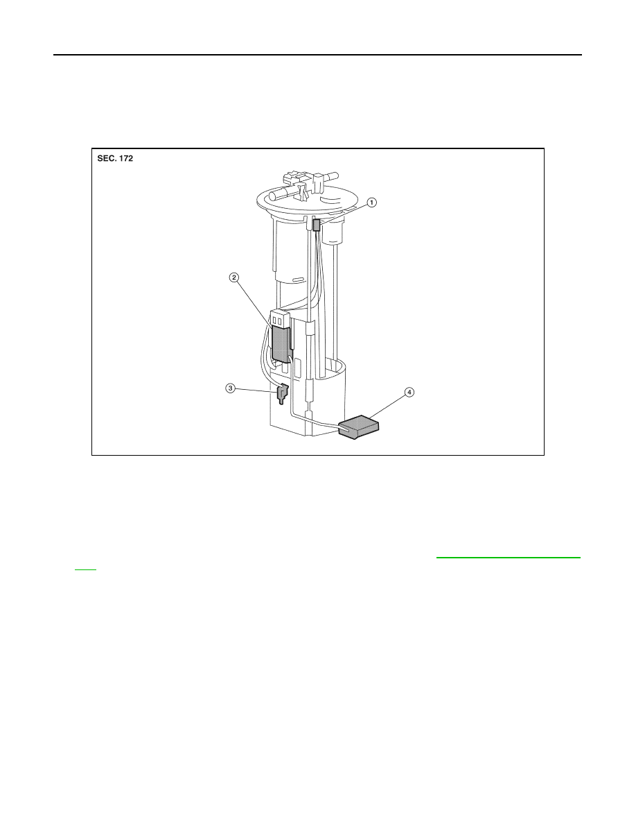
Exploded View
INFOID:0000000009886964
Fuel Level Sender Unit
Disassembly and Assembly
INFOID:0000000009886965
Disassembly
1. Remove fuel level sensor unit, fuel filter anf fuel pump assembly. Refer to
2. Remove the fuel sensor from the pump assembly.
3. Remove the sending unit module and float arm assembly.
Assembly
Assembly is the reverse order of disassembly.
AWBIA0680ZZ
1.
Harness connector
2.
Sending unit module
3.
Fuel sensor
4.
Float arm assembly