Nissan Titan. Manual - part 349
FL-14
< UNIT REMOVAL AND INSTALLATION >
FUEL LEVEL SENSOR UNIT, FUEL FILTER AND FUEL PUMP ASSEMBLY
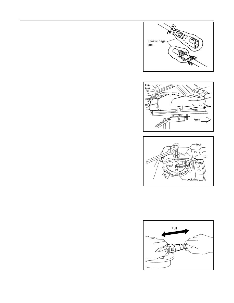
• To keep the quick connector clean and to avoid damage
and contamination from foreign materials, cover the quick
connector with plastic bags or suitable material as shown.
8. Remove the four bolts and remove the fuel tank shield using power tool.
9. Remove the fuel tank strap bolts while supporting the fuel tank
with a suitable lift jack.
10. Lower the fuel tank using a suitable lift jack and remove it from
the vehicle to access the fuel level sensor, fuel filter, and fuel
pump assembly.
11. Remove the lock ring using Tool as shown.
12. Remove the fuel level sensor, fuel filter, and fuel pump assem-
bly. Remove and discard the O-ring.
CAUTION:
• Do not bend the float arm during removal.
• Avoid impacts such as dropping when handling the com-
ponents.
• Do not reuse O-ring.
INSTALLATION
Installation is in the reverse order of removal.
CAUTION:
Do not reuse O-ring.
• Connect the quick connector as follows:
- Check the connection for any damage or foreign materials.
- Align the connector with the pipe, then insert the connector straight into the pipe until a click is heard.
- After connecting the quick connector, make sure that the connec-
tion is secure by checking as follows:
- Pull the tube and the connector to make sure they are securely
connected.
- Visually inspect the connector to make sure the two retainer tabs
are securely connected.
INSPECTION AFTER INSTALLATION
1. Turn the ignition switch ON but do not start engine, then check the fuel pipes and hose connections for
leaks while applying fuel pressure to the system.
PBIC0163E
LBIA0387E
Tool number
: — (J-46536)
LBIA0407E
PBIC1653E