Nissan Titan. Manual - part 165


  Index      Nissan     Nissan Titan (2014 year) - Service and Repair Manual


Search            


Content   ..  163  164  165  166   ..


Nissan Titan. Manual - part 165


DLN-232

< DTC/CIRCUIT DIAGNOSIS >

[REAR FINAL DRIVE: M226 (ELD) ]

P1850 SOLENOID CURRENT

P1850 SOLENOID CURRENT

Description

INFOID:0000000009886136

The differential lock control unit supplies power and ground to the differential lock solenoid via the differential

lock solenoid relay (integral to the differential lock control unit). 

DTC Logic

INFOID:0000000009886137

Diagnosis Procedure

INFOID:0000000009886138

Regarding Wiring Diagram information, refer to 

DLN-238, "Wiring Diagram"

.

1.

CHECK DIFFERENTIAL SOLENOID CONTROL

1. Start engine.

2. Using CONSULT, select “RELAY ON”, “RELAY MTR”, “SOL MTR” of DIFF LOCK data monitor.

3. Observe the display values while operating the differential lock system.

Is the inspection result normal?

YES

 >> Differential lock solenoid control system is operating normally.

NO

>> GO TO 2.

2.

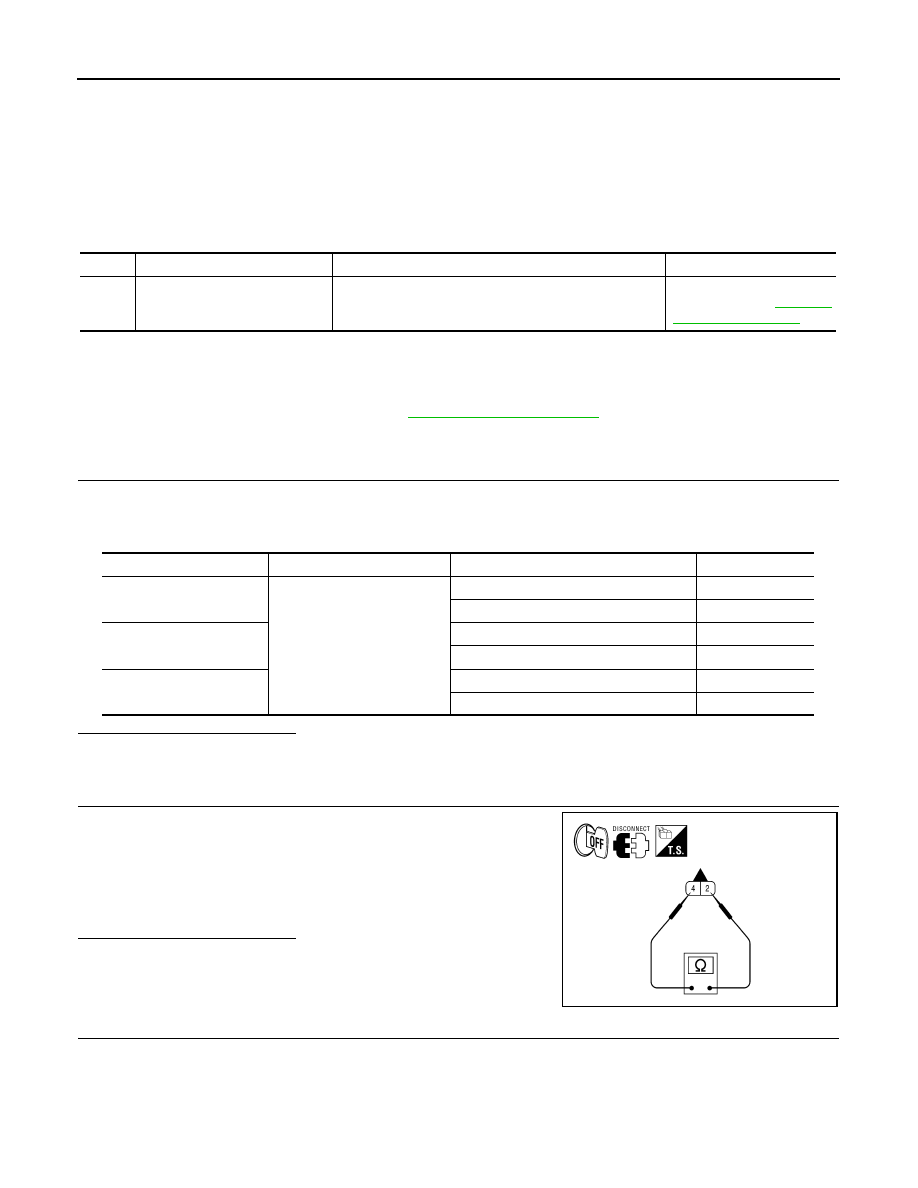
CHECK DIFFERENTIAL LOCK SOLENOID RESISTANCE

1. Turn ignition switch OFF.

2. Disconnect differential lock solenoid connector.

3. Check resistance between differential lock solenoid terminals 2

and 4.

Is the inspection result normal?

YES

>> GO TO 3.

NO

>> Replace differential lock solenoid.

3.

CHECK DIFFERENTIAL LOCK SOLENOID OPERATION

DTC

Display contents of CONSULT

DTC Detection Condition

Action to take

P1850

SOL CURRENT
[P1850]

The differential lock relay does not switch to OFF or there 
is a short to power in the harness. 

Inspect the differential lock 
solenoid. Refer to 

DLN-232, 

"Diagnosis Procedure"

.

Monitor item

Condition

Differential lock mode switch

Display value

RELAY ON

• Vehicle stopped
• Engine running
• VDC OFF switch (if 

equipped): ON

• 4WD shift switch: 4LO

ON

ON

OFF

OFF

RELAY MTR

ON

ON

OFF

OFF

SOL MTR

ON

ON

OFF

OFF

2 - 4

: Approx. 3.4

AWDIA0394ZZ

P1850 SOLENOID CURRENT

DLN-233

< DTC/CIRCUIT DIAGNOSIS >

[REAR FINAL DRIVE: M226 (ELD) ]

C

E

F

G

H

I

J

K

L

M

A

B

DLN

N

O

P

Check operation by applying power and ground to the differential

lock solenoid terminals.

Is the inspection result normal?

YES

>> GO TO 4.

NO

>> Check for a mechanical malfunction with the differential

lock system. Replace differential lock solenoid.

4.

CHECK DIFFERENTIAL LOCK SOLENOID CIRCUIT

1. Disconnect differential lock control unit connector.

2. Check continuity between differential lock control unit connector

B77 (A) terminals 11, 12 and differential lock solenoid connector

C17 (B) terminals 2, 4.

3. Check continuity between differential lock control unit connector

B77 (A) terminals 11, 12 and ground.

Is the inspection result normal?

 YES

>> Replace the differential lock control unit. Refer to 

DLN-251, "Removal and Installation"

.

 NO

>> Repair harness or connector.

Component

(+)

(-)

Solenoid operation

Terminal

Terminal

Differential lock 

solenoid

2

4

Yes

AWDIA0395ZZ

A

B

Continuity

Connector

Terminal

Connector

Terminal

B77

11

C17

2

Yes

12

4

A

Continuity

Connector

Terminal

B77

11

Ground

No

12

AWDIA0396ZZ

DLN-234

< DTC/CIRCUIT DIAGNOSIS >

[REAR FINAL DRIVE: M226 (ELD) ]

C1203 ABS SYSTEM

C1203 ABS SYSTEM

Description

INFOID:0000000009886139

The differential lock control unit and the ABS actuator and electric unit (control unit) are in communication via

the CAN communication network. Vehicle speed and wheel slippage information is used by the differential lock

control unit to determine if conditions are met to actuate the differential lock solenoid. 

DTC Logic

INFOID:0000000009886140

DTC

Display contents of CONSULT

DTC Detection Condition

Action to take

C1203

ABS SYSTEM
[C1203]

A malfunction related to wheel speed sensors has been 
detected by the ABS actuator and electric unit (control 
unit). 

Check for proper ABS oper-
ation. Refer to 

BRC-24, 

"CONSULT Function 
(ABS)"

.

LOCK INDICATOR LAMP

DLN-235

< DTC/CIRCUIT DIAGNOSIS >

[REAR FINAL DRIVE: M226 (ELD) ]

C

E

F

G

H

I

J

K

L

M

A

B

DLN

N

O

P

LOCK INDICATOR LAMP

Description

INFOID:0000000009886141

The DIFF LOCK indicator lamp has power available to it any time the ignition switch is in the ON or START

position. The differential lock control unit supplies ground to activate the DIFF LOCK indicator lamp. The DIFF

LOCK indicator lamp will go through a prove out at initial key ON. The DIFF LOCK will flash while the differen-

tial lock system is activating or while waiting for conditions to be met to activate. Once the differential lock has

been engaged, the DIFF LOCK indicator lamp will remain ON. For more information about the DIFF LOCK

indicator lamp, refer to the Owner’s Manual. 

Diagnosis Procedure

INFOID:0000000009886142

Regarding Wiring Diagram information, refer to 

DLN-238, "Wiring Diagram"

.

1.

CHECK DIFF LOCK INDICATOR LAMP OPERATION

1. Turn the ignition switch ON.

2. Observe the DIFF LOCK indicator lamp.

Is the inspection result normal?

YES

>> DIFF LOCK indicator lamp is operating normally.

NO, ALWAYS ON>> Perform self diagnostics on differential lock control unit. Refer to 

DLN-214, "CONSULT

Function (DIFF LOCK)"

.

NO, ALWAYS OFF>>GO TO 2.

2.

CHECK DIFFERENTIAL LOCK CONTROL UNIT POWER AND GROUND SUPPLY

Check the differential lock control unit power and ground supply. Refer to 

DLN-217, "Diagnosis Procedure"

.

Is the inspection result normal?

YES

>> GO TO 3.

NO

>> Repair or replace malfunctioning component. 

3.

CHECK HARNESS BETWEEN DIFFERENTIAL LOCK CONTROL UNIT AND COMBINATION METER

1. Turn ignition switch OFF.

2. Disconnect differential lock control unit connector and combina-

tion meter connector.

3. Check continuity between differential lock control unit connector

B77 (A) terminal 21 and combination meter connector M24 (B)

terminal 14.

4. Check continuity between differential lock control unit connector

B77 (A) terminal 21 and ground.

Is the inspection result normal?

YES

 >> Check DIFF LOCK indicator lamp bulb and power supply. Refer to 

DLN-208, "Work Flow"

.

NO

>> Repair harness or connector.

Ignition switch ON

Indicator prove out

Differential lock control unit

Combination meter

Continuity

Connector

Terminal

Connector

Terminal

B77

21

M24

14

Yes

Differential lock control unit

Continuity

Connector

Terminal

B77

21

Ground

Yes

AWDIA0397ZZ


Content   ..  163  164  165  166   ..