Nissan Titan. Manual - part 144
DLN-148
< UNIT REMOVAL AND INSTALLATION >
[PROPELLER SHAFT: 3S1410]
REAR PROPELLER SHAFT
UNIT REMOVAL AND INSTALLATION
REAR PROPELLER SHAFT
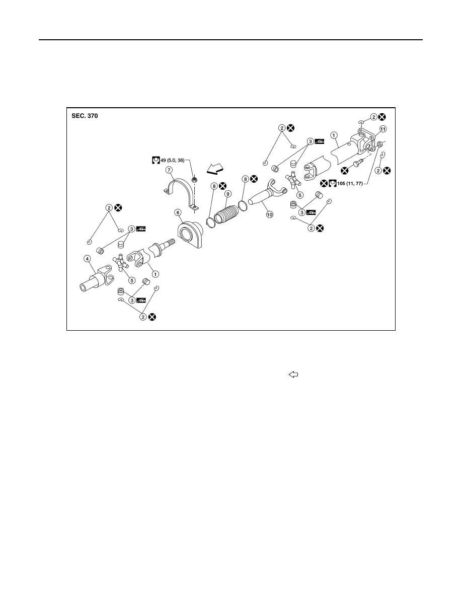
Removal and Installation
INFOID:0000000009886065
2WD Models (short wheel base)
AWDIA1050ZZ
1.
Propeller shaft tube
2.
Snap ring
3.
Journal bearing
4.
Sleeve yoke
5.
Journal
6.
Center support bearing
7.
Center support bearing bracket
8.
Clamp
9.
Boot
10. Slip yoke
11. Flange yoke
Front