Nissan Titan. Manual - part 43
WHEEL SENSORS
BRC-113
< UNIT REMOVAL AND INSTALLATION >
[VDC/TCS/ABS]
C
D
E
G
H
I
J
K
L
M
A
B
BRC
N
O
P
UNIT REMOVAL AND INSTALLATION
WHEEL SENSORS
Removal and Installation
INFOID:0000000009883744
FRONT WHEEL SENSOR
Removal
1. Remove wheel sensor bolt.
• When removing the front wheel sensor, first remove the disc rotor to gain access to the front wheel sen-
sor bolt. Refer to
BR-32, "Removal and Installation of Brake Caliper and Rotor"
.
2. Pull out the sensor, being careful to turn it as little as possible.
CAUTION:
• Be careful not to damage sensor edge and sensor rotor teeth.
• Do not pull on the sensor harness.
3. Disconnect wheel sensor harness connector, then remove harness from attaching points.
Installation
Installation is in the reverse order of removal.
CAUTION:
• Inspect wheel sensor O-ring, replace sensor assembly if damaged.
• Clean wheel sensor hole and mating surface with brake cleaner and a lint-free shop rag.
• Apply a coat of suitable grease to the wheel sensor O-ring and hole.
REAR WHEEL SENSOR
Removal
1. Remove wheel sensor bolt.
2. Pull out the sensor, being careful to turn it as little as possible.
CAUTION:
• Be careful not to damage sensor edge and sensor rotor teeth.
• Do not pull on the sensor harness.
3. Disconnect wheel sensor harness connector, then remove harness from attaching points.
Installation
1. Installation is in the reverse order of removal.
CAUTION:
• Inspect wheel sensor O-ring, replace sensor assembly if damaged.
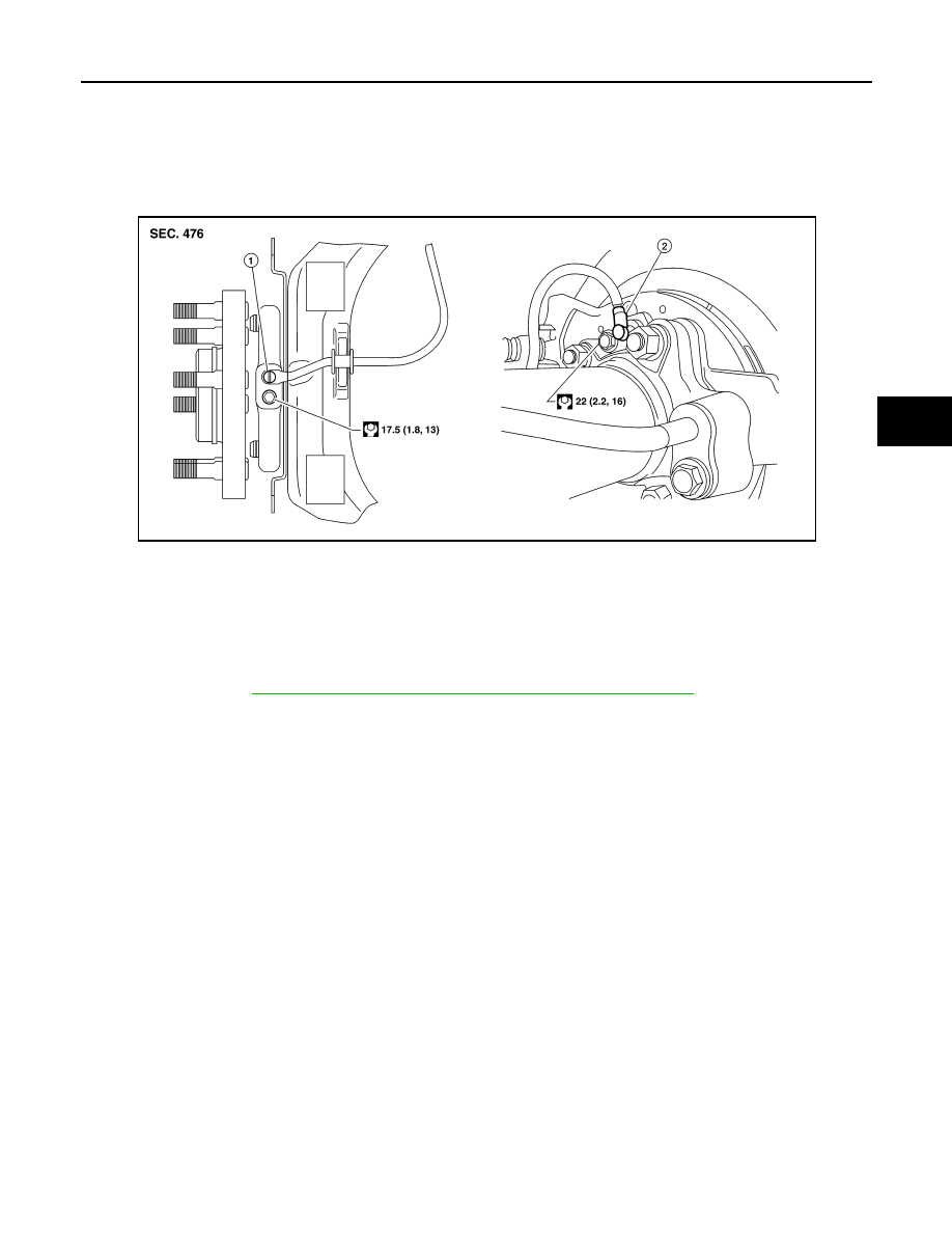
1.
Front wheel sensor
2.
Rear wheel sensor
AWFIA0959ZZ