Nissan Titan. Manual - part 42


  Index      Nissan     Nissan Titan (2014 year) - Service and Repair Manual


Search            


Content   ..  40  41  42  43   ..


Nissan Titan. Manual - part 42


PRECAUTIONS

BRC-109

< PRECAUTION >

[VDC/TCS/ABS]

C

D

E

G

H

I

J

K

L

M

A

B

BRC

N

O

P

PRECAUTION

PRECAUTIONS

Precaution for Supplemental Restraint System (SRS) "AIR BAG" and "SEAT BELT 
PRE-TENSIONER"

INFOID:0000000009883738

The Supplemental Restraint System such as “AIR BAG” and “SEAT BELT PRE-TENSIONER”, used along

with a front seat belt, helps to reduce the risk or severity of injury to the driver and front passenger for certain

types of collision. This system includes seat belt switch inputs and dual stage front air bag modules. The SRS

system uses the seat belt switches to determine the front air bag deployment, and may only deploy one front

air bag, depending on the severity of a collision and whether the front occupants are belted or unbelted.

Information necessary to service the system safely is included in the SR and SB section of this Service Man-

ual.

WARNING:

• To avoid rendering the SRS inoperative, which could increase the risk of personal injury or death in

the event of a collision which would result in air bag inflation, all maintenance must be performed by

an authorized NISSAN/INFINITI dealer.

• Improper maintenance, including incorrect removal and installation of the SRS, can lead to personal

injury caused by unintentional activation of the system. For removal of Spiral Cable and Air Bag

Module, see the SR section.

• Do not use electrical test equipment on any circuit related to the SRS unless instructed to in this

Service Manual. SRS wiring harnesses can be identified by yellow and/or orange harnesses or har-

ness connectors.

PRECAUTIONS WHEN USING POWER TOOLS (AIR OR ELECTRIC) AND HAMMERS

WARNING:

• When working near the Airbag Diagnosis Sensor Unit or other Airbag System sensors with the Igni-

tion ON or engine running, DO NOT use air or electric power tools or strike near the sensor(s) with a

hammer. Heavy vibration could activate the sensor(s) and deploy the air bag(s), possibly causing

serious injury.

• When using air or electric power tools or hammers, always switch the Ignition OFF, disconnect the

battery and wait at least 3 minutes before performing any service.

Precaution for Brake System

INFOID:0000000009883739

CAUTION:

• Always use recommended brake fluid. Refer to 

MA-15, "FOR NORTH AMERICA : Fluids and Lubri-

cants"

 (United States and Canada), 

MA-16, "FOR MEXICO : Fluids and Lubricants"

 (Mexico).

• Do not reuse drained brake fluid.

• Be careful not to splash brake fluid on painted areas; it may cause paint damage. If brake fluid is

splashed on painted areas, wash it away with water immediately. 

• To clean or wash all parts of master cylinder and disc brake caliper, use clean brake fluid.

• Do not use mineral oils such as gasoline or kerosene. They will ruin rubber parts of the hydraulic

system. 

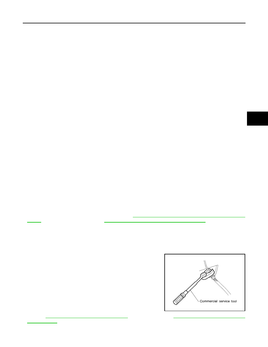
• Use flare nut wrench when removing and installing brake

tube. 

• If a brake fluid leak is found, the part must be disassembled

without fail. Then it has to be replaced with a new one if a

defect exists. 

• Turn the ignition switch OFF and remove the connector of the

ABS actuator and electric unit (control unit) or the battery ter-

minal before performing the work. 

• Always torque brake lines when installing.

• Burnish the brake contact surfaces after refinishing or replac-

ing rotors, after replacing pads, or if a soft pedal occurs at

very low mileage.

Refer to 

BR-31, "Brake Burnishing Procedure"

 (front disc brake) or 

BR-35, "Removal and Installation

of Brake Pad"

 (rear disc brake).

WARNING:

SBR686C

BRC-110

< PRECAUTION >

[VDC/TCS/ABS]

PRECAUTIONS

• Clean brake pads and shoes with a waste cloth, then wipe with a dust collector.

Precaution for Brake Control

INFOID:0000000009883740

• During ABS operation, the brake pedal may vibrate lightly and a mechanical noise may be heard. This is

normal.

• Just after starting vehicle, the brake pedal may vibrate or a motor operating noise may be heard from engine

compartment. This is a normal status of operation check.

• Stopping distance may be longer than that of vehicles without ABS when vehicle drives on rough, gravel, or

snow-covered (fresh, deep snow) roads.

• When an error is indicated by ABS or another warning lamp, collect all necessary information from customer

(what symptoms are present under what conditions) and check for simple causes before starting diagnosis.

Besides electrical system inspection, check booster operation, brake fluid level, and fluid leaks.

• If incorrect tire sizes or types are installed on the vehicle or brake pads are not Genuine NISSAN parts, stop-

ping distance or steering stability may deteriorate.

• If there is a radio, antenna or related wiring near control module, ABS function may have a malfunction or

error.

• If aftermarket parts (car stereo, CD player, etc.) have been installed, check for incidents such as harness

pinches, open circuits or improper wiring.

• If the following components are replaced with non-genuine components or modified, the VDC OFF indicator

lamp and SLIP indicator lamp may turn on or the VDC system may not operate properly. Components

related to suspension (shock absorbers, struts, springs, bushings, etc.), tires, wheels (exclude specified

size), components related to brake system (pads, rotors, calipers, etc.), components related to engine (muf-

fler, ECM, etc.), components related to body reinforcement (roll bar, tower bar, etc.).

• Driving with broken or excessively worn suspension components, tires or brake system components may

cause the VDC OFF indicator lamp and the SLIP indicator lamp to turn on, and the VDC system may not

operate properly.

• When the TCS or VDC is activated by sudden acceleration or sudden turn, some noise may occur. The

noise is a result of the normal operation of the TCS and VDC.

• When driving on roads which have extreme slopes (such as mountainous roads) or high banks (such as

sharp curves on a freeway), the VDC may not operate normally, or the VDC warning lamp and the SLIP indi-

cator lamp may turn on. This is not a problem if normal operation can be resumed after restarting the engine.

• Sudden turns (such as spin turns, acceleration turns), drifting, etc. with VDC turned off may cause the yaw

rate/side/decel G sensor to indicate a problem. This is not a problem if normal operation can be resumed

after restarting the engine.

Precaution for CAN System

INFOID:0000000009883741

• Do not apply voltage of 7.0V or higher to terminal to be measured.

• Maximum open terminal voltage of tester in use must be less than 7.0V.

• Before checking harnesses, turn ignition switch OFF and disconnect battery negative cable.

• Area to be repaired must be soldered and wrapped with tape.

Make sure that fraying of twisted wire is within 110 mm (4.33 in).

PKIA0306E

PRECAUTIONS

BRC-111

< PRECAUTION >

[VDC/TCS/ABS]

C

D

E

G

H

I

J

K

L

M

A

B

BRC

N

O

P

• Do not make a bypass connection to repaired area. (If the circuit is

bypassed, characteristics of twisted wire will be lost.)

PKIA0307E

BRC-112

< PREPARATION >

[VDC/TCS/ABS]

PREPARATION

PREPARATION

PREPARATION

Special Service Tool

INFOID:0000000009883742

The actual shapes of Kent-Moore tools may differ from those of special service tools illustrated here.

Commercial Service Tool

INFOID:0000000009883743

Tool number
(Kent-Moore No.)
Tool name

Description

KV991J0080
(J-45741)
ABS active wheel sensor tester

Checking operation of ABS active wheel sen-
sors

WFIA0101E

Tool name

Description

1. Flare nut crowfoot
2. Torque wrench

Removing and installing brake piping
a: 10 mm (0.39 in)/12 mm (0.47 in)

Power tool

Loosening nuts, screws and bolts

S-NT360

PIIB1407E


Content   ..  40  41  42  43   ..