Nissan Titan. Manual - part 6
BR-14
< PERIODIC MAINTENANCE >
BRAKE PEDAL
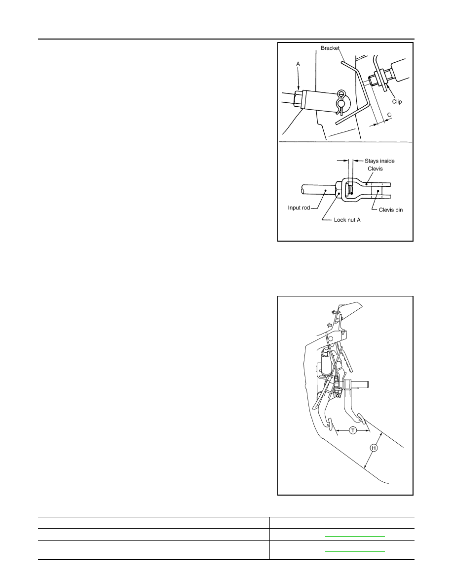
2. Loosen lock nut (A) on the input rod, then turn input rod to adjust
the brake pedal to specified height. When finished adjusting,
tighten lock nut (A) to specification.
CAUTION:
Make sure that the screw portion of the end of input rod is
located inside the clevis.
3. With the brake pedal pulled up and held by hand, press the stop
lamp switch and the ASCD cancel switch (if equipped) in until
threaded ends contact the brake pedal bracket.
4. With the threaded ends of the stop lamp switch and ASCD can-
cel switch (if equipped) contacting the pedal bracket, turn the
switches 45
° clockwise to lock in place. Check that the stop
lamp switch and ASCD cancel switch (if equipped) threaded end
to brake pedal bracket gap (C) is within specifications.
CAUTION:
Make sure that the gap (C) between the brake pedal bracket
and stop lamp switch and ASCD cancel switch (if equipped)
threaded ends are within specification.
5. Check the brake pedal for smooth operation.
CAUTION:
Make sure that the stop lamp goes off when the brake pedal
is released.
Inspection and Adjustment - Adjustable Pedal
INFOID:0000000009883537
INSPECTION
1. Inspect the brake pedal free height (H) from the floor using Tool
at a 90
° angle to the floor as shown.
CAUTION:
When equipped with adjustable pedal, the pedal must be in
the forward most (closest to the floor) position for pedal
height measurement.
2. Adjust the height referring to the following specifications.
Brake Pedal Specifications
Unit: mm (in)
Lock nut (A)
: 18.7 N·m (1.9 kg-m, 14 ft-lb)
PFIA0436E
Tool number :
—
(J-46532)
ALFIA0149ZZ
Pedal free height (H) with pedal in forward most position
Refer to
Pedal full stroke (T)
Refer to
Clearance between brake pedal bracket and threaded end of stop lamp switch and
ASCD cancel switch
Refer to