Nissan Titan A60. Manual - part 984


  Index      Nissan     Nissan Titan A60 (2011 year) - Service and Repair Manual


Search            


Content   ..  982  983  984  985   ..


Nissan Titan A60. Manual - part 984


WCS

DIAGNOSIS SYSTEM (METER)

WCS-11

< SYSTEM DESCRIPTION >

C

D

E

F

G

H

I

J

K

L

M

B

A

O

P

DIAGNOSIS SYSTEM (METER)

CONSULT-III Function (METER/M&A)

INFOID:0000000006625828

CONSULT-III can display each diagnostic item using the diagnostic test modes shown following.

SELF-DIAG RESULTS

Display Item List

Refer to 

MWI-45, "DTC Index"

.

DATA MONITOR

Display Item List

X: Applicable

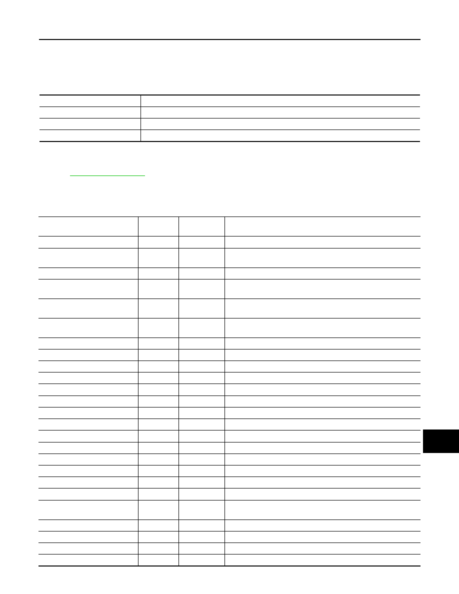
METER/M&A diagnosis mode

Description

SELF DIAGNOSTIC RESULT

Displays combination meter self-diagnosis results.

DATA MONITOR

Displays combination meter input/output data in real time.

CAN DIAG SUPPORT MNTR

The result of transmit/receive diagnosis of CAN communication can be read.

Display item [Unit]

MAIN

SIGNALS

SELECTION 

FROM MENU

Description

SPEED METER [km/h] or [mph]

X

X

Displays the value of vehicle speed signal.

SPEED OUTPUT [km/h] or [mph]

X

X

Displays the value of vehicle speed signal, which is transmitted to 
each unit with CAN communication.

TACHO METER [rpm]

X

X

Displays the value of engine speed signal, which is input from ECM.

W TEMP METER [

°C] or [°F]

X

X

Displays the value of engine coolant temperature signal, which is in-
put from ECM. 

FUEL METER [lit.]

X

X

Displays the value, which processes a resistance signal from fuel 
gauge.

DISTANCE [km] or [mile]

X

X

Displays the value, which is calculated by vehicle speed signal, fuel 
gauge and fuel consumption from ECM.

FUEL W/L [ON/OFF]

X

X

Displays [ON/OFF] condition of fuel warning lamp.

C-ENG W/L [ON/OFF] 

X

Displays [ON/OFF] condition of malfunction indicator lamp.

AIR PRES W/L [ON/OFF]

X

Displays [ON/OFF] condition of tire pressure warning lamp.

SEAT BELT W/L [ON/OFF]

X

Indicates [ON/OFF] condition of seat belt warning lamp.

BUZZER [ON/OFF]

X

X

Displays [ON/OFF] condition of buzzer.

DOOR W/L [ON/OFF]

X

Displays [ON/OFF] condition of door warning lamp.

HI-BEAM IND [ON/OFF]

X

Displays [ON/OFF] condition of high beam indicator.

TURN IND [ON/OFF]

X

Displays [ON/OFF] condition of turn indicator.

OIL W/L [ON/OFF]

X

Displays [ON/OFF] condition of oil pressure warning lamp.

VDC/TCS IND [ON/OFF]

X

Displays [ON/OFF] condition of VDC OFF indicator lamp.

ABS W/L [ON/OFF]

X

Displays [ON/OFF] condition of ABS warning lamp.

SLIP IND [ON/OFF]

X

Displays [ON/OFF] condition of SLIP indicator lamp.

BRAKE W/L [ON/OFF]

X

Displays [ON/OFF] condition of brake warning lamp.*

M RANGE SW [ON/OFF]

X

X

Displays [ON/OFF] condition of manual mode range switch.

NM RANGE SW [ON/OFF]

X

X

Displays [ON/OFF] condition of except for manual mode range 
switch.

AT SFT UP SW [ON/OFF]

X

X

Displays [ON/OFF] condition of A/T shift-up switch.

AT SFT DWN SW [ON/OFF]

X

X

Displays [ON/OFF] condition of A/T shift-down switch.

BRAKE SW [ON/OFF]

X

Indicates [ON/OFF] condition of parking brake switch.

AT-M GEAR [1, 2, 3, 4, 5]

X

X

Indicates [1, 2, 3, 4, 5] condition of A/T manual mode gear position.

WCS-12

< SYSTEM DESCRIPTION >

DIAGNOSIS SYSTEM (METER)

NOTE:
Some items are not available due to vehicle specification.
*: The monitor will indicate “OFF” even though the brake warning lamp is on if either of the following conditions exist. 
• The parking brake is engaged
• The brake fluid level is low

P RANGE IND [ON/OFF] 

X

X

Indicates [ON/OFF] condition of A/T shift P range indicator.

R RANGE IND [ON/OFF]

X

X

Indicates [ON/OFF] condition of A/T shift R range indicator.

N RANGE IND [ON/OFF]

X

X

Indicates [ON/OFF] condition of A/T shift N range indicator.

D RANGE IND [ON/OFF]

X

X

Indicates [ON/OFF] condition of A/T shift D range indicator.

4 RANGE IND [ON/OFF]

X

X

Indicates [ON/OFF] condition of A/T shift 4 range indicator.

3 RANGE IND [ON/OFF]

X

X

Indicates [ON/OFF] condition of A/T shift 3 range indicator.

2 RANGE IND [ON/OFF]

X

X

Indicates [ON/OFF] condition of A/T shift 2 range indicator.

1 RANGE IND [ON/OFF]

X

X

Indicates [ON/OFF] condition of A/T shift 1range indicator.

AT CHECK W/L [ON/OFF]

X

Displays [ON/OFF] condition of AT CHECK warning lamp.

CRUISE IND [ON/OFF]

X

Displays [ON/OFF] condition of CRUISE indicator.

SET IND [ON/OFF]

X

Displays [ON/OFF] condition of SET indicator.

CRUISE W/L [ON/OFF]

X

Indicates [ON/OFF] condition of CRUISE warning lamp.

4WD LOCK SW [ON/OFF]

X

Indicates [ON/OFF] condition of 4WD lock switch.

4WD LOCK IND [ON/OFF]

X

Indicates [ON/OFF] condition of 4WD lock indicator.

FUEL CAP W/L [ON/OFF]

X

Displays [ON/OFF] condition of loose fuel cap indicator.

TPMS PRESS L [ON/OFF]

X

Displays [ON/OFF] condition of check tire pressure indicator.

Display item [Unit]

MAIN

SIGNALS

SELECTION 

FROM MENU

Description

WCS

DIAGNOSIS SYSTEM (BCM)

WCS-13

< SYSTEM DESCRIPTION >

C

D

E

F

G

H

I

J

K

L

M

B

A

O

P

DIAGNOSIS SYSTEM (BCM)

BUZZER
BUZZER : CONSULT-III Function (BCM - BUZZER)

INFOID:0000000006625829

DATA MONITOR

ACTIVE TEST

Monitor Item [Unit]

Description

DOOR SW-DR [On/Off]

Indicates condition of front door switch LH.

IGN ON SW [On/Off]

Indicates condition of ignition switch ON position.

KEY ON SW [On/Off]

Indicates condition of key switch.

LIGHT SW 1ST [On/Off]

Indicates condition of combination switch.

BUCKLE SW [On/Off]

Indicates condition of seat belt buckle switch.

Test Item

Description

SEAT BELT WARN TEST

This test is able to check seat belt warning operation [Off/On].

LIGHT WARN ALM

This test is able to check light reminder warning operation [Off/On].

IGN KEY WARN ALM

This test is able to check key warning chime operation [Off/On].

WCS-14

< DTC/CIRCUIT DIAGNOSIS >

POWER SUPPLY AND GROUND CIRCUIT

DTC/CIRCUIT DIAGNOSIS

POWER SUPPLY AND GROUND CIRCUIT

COMBINATION METER
COMBINATION METER : Diagnosis Procedure

INFOID:0000000006625908

Regarding Wiring Diagram information, refer to 

MWI-65, "Wiring Diagram"

.

1.

CHECK FUSES

Check for blown combination meter fuses.

Is the inspection result normal?

YES

>> GO TO 2

NO

>> If fuse is blown, be sure to eliminate cause of malfunction before installing new fuse.

2.

POWER SUPPLY CIRCUIT CHECK

1. Disconnect combination meter connector M24.

2. Check voltage between combination meter harness connector

M24 terminals 1, 8, 24 and ground.

Is the inspection result normal?

YES

>> GO TO 3

NO

>> Check harness for open between combination meter and fuse.

3.

GROUND CIRCUIT CHECK

1. Turn ignition switch OFF.

2. Disconnect combination meter connector M25.

3. Check continuity between combination meter harness connector

M25 terminal 52 and ground, and connector M24 terminal 9 and

ground.

Is the inspection result normal?

Unit

Power source

Fuse No.

Combination meter

Battery 3

Ignition switch ON or START 

14

Ignition switch ACC or ON

4

Terminals

Ignition switch position

(+)

(–)

OFF

ACC

ON

START

Connector

Terminal

M24

1

Ground

0V

Battery 
voltage

Battery 
voltage

0V

8

Battery 
voltage

Battery 
voltage

Battery

 voltage

Battery 
voltage

24

0V

0V

Battery
voltage

Battery 
voltage

AWNIA0107ZZ

Terminals

Continuity

(+)

(–)

Connector

Terminal

A: M25

52

Ground

Yes

B: M24

9

AWNIA0108ZZ


Content   ..  982  983  984  985   ..