Nissan Titan A60. Manual - part 969


  Index      Nissan     Nissan Titan A60 (2011 year) - Service and Repair Manual


Search            


Content   ..  967  968  969  970   ..


Nissan Titan A60. Manual - part 969


TM-264

< UNIT DISASSEMBLY AND ASSEMBLY >

ASSEMBLY

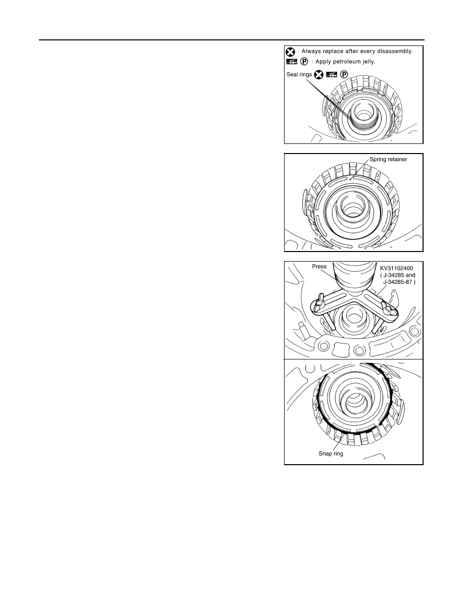
15. Install seal rings to drum support.

CAUTION:

• Do not reuse seal rings.

• Apply petroleum jelly to seal rings.

16. Install spring retainer and return spring in transmission case.

17. Install snap ring in transmission case while compressing return

spring using Tool.

CAUTION:

Securely assemble them using a flat-bladed screwdriver so

that snap ring tension is slightly weak.

18. Install revers brake drive plates driven plates and dish plates in transmission case.

CAUTION:

SCIA3333E

SCIA2324E

Tool number

: KV31102400 (J-34285 and J-34285-87)

SCIA5877E

ASSEMBLY

TM-265

< UNIT DISASSEMBLY AND ASSEMBLY >

C

E

F

G

H

I

J

K

L

M

A

B

TM

N

O

P

Take care with order of plates.

• Snap ring (1)

• Retaining plate (2)

• Drive plate (3)

• Driven plate (4)

• Dish plate (5)

• Drive plate/Driven plate: 7/7

19. Assemble N-spring.
20. Install reverse brake retaining plate in transmission case.

21. Install snap ring in transmission case.

22. Measure clearance (A) between retaining plate and snap ring. If

not within specified clearance, select proper retaining plate.

WCIA0625E

SCIA5249E

SCIA2439E

Clearance “A”

: 0.7 - 1.1mm (0.028 - 0.043 in)

Retaining plate

: Refer to 

TM-284, "Reverse 

Brake"

.

SCIA3129E

TM-266

< UNIT DISASSEMBLY AND ASSEMBLY >

ASSEMBLY

23. Install needle bearing to transmission case.

CAUTION:

• Take care with the direction of needle bearing. Refer to

TM-221, "Location of Adjusting Shims, Needle Bearings,

Thrust Washers and Snap Rings"

.

• Apply petroleum jelly to needle bearing.

24. Install output speed sensor (1) to transmission case and tighten

bolt (

) to specified torque.

CAUTION:

• Do not subject sensor to impact by dropping or hitting it.

• Do not disassemble sensor.

• Do not allow metal filings or any foreign material to get on

the sensor's front edge magnetic area.

• Do not place sensor in an area affected by magnetism.

25. As shown in the figure, use the drift to drive rear oil seal into the

rear extension (2WD models) (A) or adapter case (4WD models)

(B) until it is flush.

CAUTION:

• Apply ATF to rear oil seal.

• Do not reuse rear oil seal.

26. Install return spring (1) to parking pawl (2).

SCIA5031E

Output speed sensor bolt : 5.8 N·m (0.59 kg-m, 51 in-lb)

JSDIA1321ZZ

1

: Drift [ST33400001 (J-26082)]

2

: Drift [Commercial service tool Ø64 mm (2.52 in)]

JSDIA1914ZZ

SCIA6180J

ASSEMBLY

TM-267

< UNIT DISASSEMBLY AND ASSEMBLY >

C

E

F

G

H

I

J

K

L

M

A

B

TM

N

O

P

27. Install parking pawl (with return spring) and pawl shaft to rear

extension (2WD models) or adapter case (4WD models).

28. Install parking actuator support to rear extension (2WD models)

or adapter case (4WD models).

29. Install needle bearing (1) to rear extension (2WD models) or

adapter case (4WD models).

CAUTION:

Apply petroleum jelly to needle bearing.

30. Install seal rings to output shaft.

CAUTION:

• Do not reuse seal rings.

• Apply petroleum jelly to seal rings.

31. Install parking gear to output shaft.

SCIA3424E

SCIA3423E

SCIA6179J

SCIA5209E

SCIA5247E


Content   ..  967  968  969  970   ..