Nissan Titan A60. Manual - part 607


  Index      Nissan     Nissan Titan A60 (2011 year) - Service and Repair Manual


Search            


Content   ..  605  606  607  608   ..


Nissan Titan A60. Manual - part 607


DIAGNOSIS SYSTEM (HVAC)

HAC-111

< SYSTEM DESCRIPTION >

[MANUAL A/C (TYPE 1)]

C

D

E

F

G

H

J

K

L

M

A

B

HAC

N

O

P

DIAGNOSIS SYSTEM (HVAC)

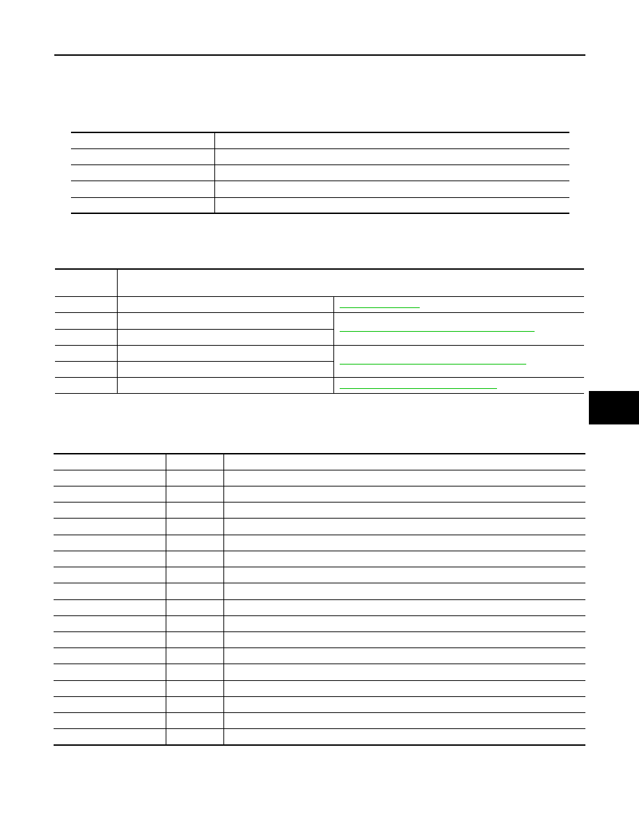
CONSULT-III Function (HVAC)

INFOID:0000000006164747

CONSULT-III can display each diagnostic item using the diagnostic test modes shown following.

SELF-DIAGNOSIS

Display Item List

DATA MONITOR

Display Item List

Diagnostic mode

Description

SELF DIAGNOSTIC RESULT 

Displays Front air control self-diagnosis results.

DATA MONITOR

Displays Front air control input/output data in real time.

CAN DIAG SUPPORT MNTR

The result of transmit/receive diagnosis of CAN communication can be read.

ECU IDENTIFICATION

Front air control part number can be read.

DTC

Description

Reference page

B2573

Battery voltage out of range

CHG-4, "Work Flow"

B257B

Ambient sensor circuit short

HAC-144, "Ambient Sensor Diagnosis Procedure"

B257C

Ambient sensor circuit open

B2581

Intake sensor circuit short

HAC-147, "Intake Sensor Diagnosis Procedure"

B2582

Intake sensor circuit open

U1000

CAN bus fault

LAN-14, "Trouble Diagnosis Flow Chart"

Monitor item

Value

Contents

BATT VIA CAN

"V"

Displays battery voltage signal.

IGN VIA CAN 

"ON/OFF"

Displays ignition switch signal.

AMB TEMP SEN

"

°C"

Displays ambient sensor signal.

EVAP TEMP SEN

"

°C"

Displays intake sensor signal.

MODE FDBCK

"V"

Displays mode door motor feedback signal.

DVR MIX FDBCK

"V"

Displays air mix door motor feedback signal.

DEF FDBCK

"V"

Displays defroster door motor feedback signal.

RECIRC

"ON/OFF"

Displays recirculation switch signal.

DEFROST

"ON/OFF"

Displays defroster switch signal.

A/C

"ON/OFF"

Displays A/C switch signal.

L TEMP UP

"ON/OFF"

Displays driver side temperature control dial (temp increase) signal.

L TEMP DOWN

"ON/OFF"

Displays driver side temperature control dial (temp decrease) signal.

RR DEFOG

"ON/OFF"

Displays rear defroster request signal.

FAN UP

"ON/OFF"

Displays blower motor (blower speed increase) signal.

FAN DOWN

"ON/OFF"

Displays blower motor (blower speed decrease) signal.

MODE SELECT

"DTNT"

Displays blower motor (blower speed decrease) signal.

FAN DOWN

"ON/OFF"

Displays blower motor (blower speed decrease) signal.

HAC-112

< SYSTEM DESCRIPTION >

[MANUAL A/C (TYPE 1)]

DIAGNOSIS SYSTEM (BCM)

DIAGNOSIS SYSTEM (BCM)

CONSULT-III Function (BCM - COMMON ITEM)

INFOID:0000000006625985

APPLICATION ITEM

CONSULT-III performs the following functions via CAN communication with BCM.

SYSTEM APPLICATION

BCM can perform the following functions.

CONSULT-III Function (BCM - AIR CONDITIONER)

INFOID:0000000006625986

DATA MONITOR

Direct Diagnostic Mode

Description

Ecu Identification

The BCM part number is displayed.

Self Diagnostic Result

The BCM self diagnostic results are displayed.

Data Monitor

The BCM input/output data is displayed in real time.

Active Test

The BCM activates outputs to test components.

Work support

The settings for BCM functions can be changed.

Configuration

• The vehicle specification can be read and saved.
• The vehicle specification can be written when replacing BCM.

CAN Diag Support Mntr

The result of transmit/receive diagnosis of CAN communication is displayed.

System

Sub System

Direct Diagnostic Mode

Ecu Id

en

tificati

on

Sel

f Di

agn

os

tic Re

su

lt

Dat

a

 M

on

ito

r

Acti

ve

 T

est

W

ork

 su

pp

ort

Co

nf

ig

ur

at

io

n

CAN Diag S

upport Mntr

Door lock

DOOR LOCK

×

×

×

×

Rear window defogger

REAR DEFOGGER

×

×

Warning chime

BUZZER

×

×

Interior room lamp timer

INT LAMP

×

×

×

Remote keyless entry system

MULTI REMOTE ENT

×

×

×

Exterior lamp

HEADLAMP

×

×

×

Wiper and washer

WIPER

×

×

×

Turn signal and hazard warning lamps FLASHER

×

×

Air conditioner

AIR CONDITIONER

×

Combination switch

COMB SW

×

BCM

BCM

×

×

×

×

×

Immobilizer

IMMU

×

×

×

Interior room lamp battery saver

BATTERY SAVER

×

×

×

Vehicle security system

THEFT ALM

×

×

×

RAP system

RETAINED PWR

×

×

×

Signal buffer system

SIGNAL BUFFER

×

×

TPMS

AIR PRESSURE MONITOR

×

×

×

×

Panic alarm system

PANIC ALARM

×

DIAGNOSIS SYSTEM (BCM)

HAC-113

< SYSTEM DESCRIPTION >

[MANUAL A/C (TYPE 1)]

C

D

E

F

G

H

J

K

L

M

A

B

HAC

N

O

P

Monitor Item [Unit]

Description

IGN ON SW [On/Off]

Indicates condition of ignition switch ON position.

FAN ON SIG [On/Off]

Indicates condition of fan switch.

AIR COND SW [On/Off]

Indicates condition of A/C switch.

HAC-114

< SYSTEM DESCRIPTION >

[MANUAL A/C (TYPE 1)]

SELF-DIAGNOSIS FUNCTION

SELF-DIAGNOSIS FUNCTION

Front Air Control Self-Diagnosis

INFOID:0000000006164751

A/C SYSTEM SELF-DIAGNOSIS FUNCTION 

The self-diagnosis function is built into the front air control to quickly locate the cause of malfunctions.

DESCRIPTION

The self-diagnostic system diagnoses sensors, CAN system, and battery voltage on front air control Refer to

applicable sections (items) for details. Fault codes (if any are present) will be displayed in the ambient temper-

ature display area (if equipped). Refer to 

HAC-114, "Front Air Control Self-Diagnosis Code Chart"

.

SELF-DIAGNOSTIC MODE

1. Rotate the blower control dial counterclockwise to the OFF posi-

tion. 

2. Press the FLOOR/DEF (

) and DEF (

) mode switches

together and release on the front air control. 

3. Press the REC (

) to enter self diagnostic mode.

4. Turn ignition switch OFF to exit out of self-diagnostic mode.

Front Air Control Self-Diagnosis Code Chart

INFOID:0000000006164752

SELF-DIAGNOSTIC CODE CHART

AWIIA0481ZZ

Code No.

Reference page

03

Battery voltage out of range

CHG-4, "Work Flow"

40

Ambient sensor circuit short

HAC-56, "Ambient Sensor Diagnosis Procedure"

41

Ambient sensor circuit open

56

Intake sensor circuit short

HAC-64, "Intake Sensor Diagnosis Procedure"

57

Intake sensor circuit open

80

CAN bus fault

LAN-14, "Trouble Diagnosis Flow Chart"

90

Stuck button

VTL-8, "Removal and Installation"


Content   ..  605  606  607  608   ..