Nissan Titan A60. Manual - part 608
MANUAL A/C IDENTIFICATION TABLE
HAC-115
< DTC/CIRCUIT DIAGNOSIS >
[MANUAL A/C (TYPE 1)]
C
D
E
F
G
H
J
K
L
M
A
B
HAC
N
O
P
DTC/CIRCUIT DIAGNOSIS
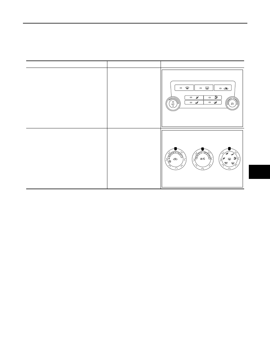
MANUAL A/C IDENTIFICATION TABLE
Application Table
INFOID:0000000006164753
Manual A/C Type
Description
Visual Identification
Manual A/C (Type 1)
Two Control Dial System
Manual A/C (Type 2)
Three Control Dial System
[with variable blower control
(VBC)]
AWIIA0481ZZ
AWIIA0478ZZ