Nissan Titan A60. Manual - part 605


  Index      Nissan     Nissan Titan A60 (2011 year) - Service and Repair Manual


Search            


Content   ..  603  604  605  606   ..


Nissan Titan A60. Manual - part 605


FUNCTION INFORMATION

HAC-103

< SYSTEM DESCRIPTION >

[MANUAL A/C (TYPE 1)]

C

D

E

F

G

H

J

K

L

M

A

B

HAC

N

O

P

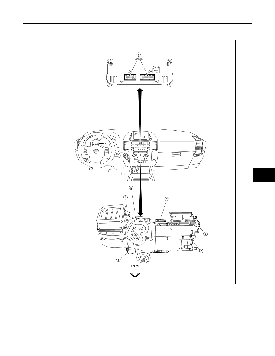
PASSENGER COMPARTMENT

1.

Front air control M180, M181

2.

Intake sensor M146

3.

Intake door motor M58

4.

Variable blower control M122

5.

Mode door motor M142

6.

Defroster door motor M144

7.

Air mix door motor  M147

AWIIA0444ZZ

HAC-104

< SYSTEM DESCRIPTION >

[MANUAL A/C (TYPE 1)]

FUNCTION INFORMATION

Symptom Table

INFOID:0000000006164740

Symptom

Reference Page

A/C system does not come on.

Go to Trouble Diagnosis Procedure for A/C System.

HAC-150

A/C system cannot be controlled.

Go to Self-diagnosis Function.

HAC-114

Air outlet does not change.

Go to Trouble Diagnosis Procedure for Mode Door Motor.

HAC-116

Mode door motor is malfunctioning.

Discharge air temperature does not change.

Go to Trouble Diagnosis Procedure for Air Mix Door Motor.

HAC-120

Air mix door motor is malfunctioning.

Intake door does not change.

Go to Trouble Diagnosis Procedure for Intake Door Motor.

HAC-126

Intake door motor is malfunctioning.

Defroster door motor is malfunctioning.

Go to Trouble Diagnosis Procedure for Defroster Door Motor.

HAC-127

Front blower motor operation is malfunctioning.

Go to Trouble Diagnosis Procedure for Front Blower Motor.

HAC-132

Magnet clutch does not engage.

Go to Trouble Diagnosis Procedure for Magnet Clutch.

HAC-137

Insufficient cooling

Go to Trouble Diagnosis Procedure for Insufficient Cooling.

HAC-167

Insufficient heating

Go to Trouble Diagnosis Procedure for Insufficient Heating.

HAC-175

Noise

Go to Trouble Diagnosis Procedure for Noise.

HAC-177

Self-diagnosis cannot be performed.

Go to Trouble Diagnosis Procedure for Self-diagnosis.

HAC-114

REFRIGERATION SYSTEM

HAC-105

< SYSTEM DESCRIPTION >

[MANUAL A/C (TYPE 1)]

C

D

E

F

G

H

J

K

L

M

A

B

HAC

N

O

P

REFRIGERATION SYSTEM

Refrigerant Cycle

INFOID:0000000006164741

REFRIGERANT FLOW

The refrigerant flows in the standard pattern, that is, through the compressor, the condenser with liquid tank,

through the evaporator, and back to the compressor. The refrigerant evaporation through the evaporator coils

are controlled by externally equalized expansion valve, located inside the evaporator case.

Refrigerant System Protection

INFOID:0000000006164742

REFRIGERANT PRESSURE SENSOR

The refrigerant system is protected against excessively high or low pressures by the refrigerant pressure sen-

sor, located on the condenser. If the system pressure rises above or falls below the specifications, the refriger-

ant pressure sensor detects the pressure inside the refrigerant line and sends a voltage signal to the ECM.

The ECM de-energizes the A/C relay to disengage the magnetic compressor clutch when pressure on the high
pressure side detected by refrigerant pressure sensor is over about 2,746 kPa (28 kg/cm

2

, 398 psi), or below

about 120 kPa (1.22 kg/cm

2

, 17.4 psi).

PRESSURE RELIEF VALVE

The refrigerant system is also protected by a pressure relief valve, located in the rear head of the compressor.

When the pressure of refrigerant in the system increases to an abnormal level [more than 2,990 kPa (30.5 kg/

HAC-106

< SYSTEM DESCRIPTION >

[MANUAL A/C (TYPE 1)]

REFRIGERATION SYSTEM

cm

2

, 433.6 psi)], the release port on the pressure relief valve automatically opens and releases refrigerant into

the atmosphere.

WJIA1347E


Content   ..  603  604  605  606   ..