Nissan Titan A60. Manual - part 499


  Index      Nissan     Nissan Titan A60 (2011 year) - Service and Repair Manual


Search            


Content   ..  497  498  499  500   ..


Nissan Titan A60. Manual - part 499


PARKING LAMP CIRCUIT

EXL-51

< DTC/CIRCUIT DIAGNOSIS >

C

D

E

F

G

H

I

J

K

M

A

B

EXL

N

O

P

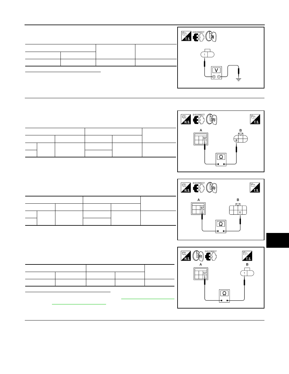
7. With the parking lamps ON, check voltage between the license

plate lamp connector and ground

Are voltage readings as specified?

YES

>> GO TO 4.

NO

>> GO TO 3.

3.

CHECK PARKING, LICENSE PLATE AND TAIL LAMP CIRCUIT (OPEN)

1. Turn the ignition switch OFF.

2. Disconnect IPDM E/R connector E124.

3. Check continuity between the IPDM E/R harness connector (A)

and the front combination lamp harness connector (B).

4. Check continuity between the IPDM E/R harness connector (A)

and the rear combination lamp harness connector (B).

5. Check continuity between the IPDM E/R harness connector (A)

and license plate lamp connector (B). 

Are continuity test results as specified?

YES

>> Replace IPDM E/R. Refer to 

PCS-28, "Removal and

Installation of IPDM E/R"

.

NO

>> Repair the harnesses or connectors.

4.

CHECK PARKING, LICENSE AND TAIL LAMP GROUND CIRCUITS

(+)

(

−)

Voltage

Connector

Terminal

C12

1

Ground

Battery voltage

ALLIA0571ZZ

A

B

Continuity

Connector

Terminal

Connector

Terminal

LH

E124

57

E6

6

Yes

RH

E108

ALLIA0396ZZ

A

B

Continuity

Connector

Terminal

Connector

Terminal

LH

E124

57

C13

6

Yes

RH

C14

AWLIA1614ZZ

A

B

Continuity

Connector

Terminal

Connector

Terminal

E124

57

C12

1

Yes

ALLIA0573ZZ

EXL-52

< DTC/CIRCUIT DIAGNOSIS >

PARKING LAMP CIRCUIT

1. Check continuity between the front combination lamp harness

connectors E6 and E108 terminal 4 and ground.

2. Check continuity between the rear combination lamp harness

connectors and ground.

3. Check continuity between the license plate lamp harness con-

nector and ground.

Does continuity exist?

YES

>> Inspect the parking lamp bulb.

NO

>> Repair the harness.

Connector

Terminal

Continuity

LH

E6

4

Ground

Yes

RH

E108

ALLIA0399ZZ

Connector

Terminal

Continuity

LH

C13

1

Ground

Yes

RH

C14

AWLIA1615ZZ

Connector

Terminal

Continuity

C12

2

Ground

Yes

ALLIA0575ZZ

TURN SIGNAL LAMP CIRCUIT

EXL-53

< DTC/CIRCUIT DIAGNOSIS >

C

D

E

F

G

H

I

J

K

M

A

B

EXL

N

O

P

TURN SIGNAL LAMP CIRCUIT

Description

INFOID:0000000006179037

The BCM monitors inputs from the combination switch (lighting and turn signal switch) to determine when to

activate the turn signals. The BCM outputs voltage direction to the left and right turn signals during turn signal

operation or both during hazard warning operation. The BCM sends a turn signal indicator request to the com-

bination meter via the CAN communication lines. 

The BCM performs the fast flasher operation (fail-safe) if any bulb or harness of the turn signal lamp circuit is

open.

NOTE:

Turn signal lamp blinks at normal speed when using the hazard warning lamp.

Component Function Check

INFOID:0000000006179038

1.

CHECK TURN SIGNAL LAMP

CONSULT-III

1. Select "FLASHER" of BCM (FLASHER) active test item.

2. With operating the test items, check that the turn signal lamp blinks.

Does the turn signal lamp blink?

YES

>> Turn signal lamp circuit is normal.

NO

>> Refer to 

EXL-53, "Diagnosis Procedure - Without Daytime Light System"

EXL-56, "Diagnosis

Procedure - With Daytime Light System"

.

Diagnosis Procedure - Without Daytime Light System

INFOID:0000000006709932

Regarding Wiring Diagram information, refer to 

EXL-100, "Wiring Diagram"

.

1.

CHECK TURN SIGNAL LAMP BULB

Check the applicable lamp bulb to be sure the proper bulb standard is in use and the bulb is not open.
Is the bulb OK?

YES

>> GO TO 2.

NO

>> Replace the bulb.

2.

CHECK TURN SIGNAL LAMP OUTPUT VOLTAGE

1. Turn the ignition switch OFF.

2. Disconnect the front combination lamp connector, door mirror connector (if equipped with turn signals in

the mirrors) and the rear combination lamp connector.

3. Turn the ignition switch ON.

4. With turn signal switch operating, check the voltage between the front combination lamp harness connec-

tor and ground.

LH

: Turn signal lamp LH blinking 

RH

: Turn signal lamp RH blinking 

OFF

: The turn signal lamp OFF

(+)

(

−)

Voltage

Connector

Terminal

EXL-54

< DTC/CIRCUIT DIAGNOSIS >

TURN SIGNAL LAMP CIRCUIT

5. With turn signal switch operating, check the voltage between the rear combination lamp harness connec-

tor and ground.

6. With turn signal switch operating, check the voltage between the door mirror (if equipped with turn signals

in the mirrors) harness connector and ground.

Is voltage reading as specified?

YES

>> GO TO 5.

NO

>> GO TO 3.

3.

CHECK TURN SIGNAL LAMP CIRCUIT FOR OPEN 

1. Turn the ignition switch OFF.

2. Disconnect BCM connector M20.

3. Check continuity between the BCM harness connector (A) and

the front combination lamp connector (B).

E11

LH

5

Ground

E107

RH

(+)

(

−)

Voltage

Connector

Terminal

C13

LH

8

Ground

C14

RH

(+)

(

−)

Voltage

Connector

Terminal

D4

LH

15

Ground

D107

RH

PKID0926E

PKID0926E

PKID0926E

A

B

Continuity

Connector

Terminal

Connector

Terminal

Front LH

M20

60

E11

5

Yes

Front RH

61

E107

ALLIA0403GB


Content   ..  497  498  499  500   ..