Nissan Titan A60. Manual - part 469


  Index      Nissan     Nissan Titan A60 (2011 year) - Service and Repair Manual


Search            


Content   ..  467  468  469  470   ..


Nissan Titan A60. Manual - part 469


CAMSHAFT

EM-61

< REMOVAL AND INSTALLATION >

C

D

E

F

G

H

I

J

K

L

M

A

EM

N

P

O

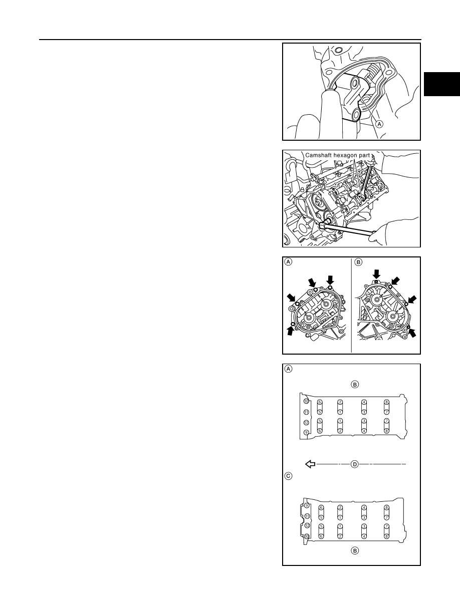
c. Remove the bolts and the chain tensioner (RH) (A).

NOTE:

If it is difficult to push plunger on chain tensioner (RH) (A),

remove the plunger under extended condition.

14. Loosen camshaft sprocket bolts as shown and remove camshaft

sprockets.

CAUTION:

To avoid interference between valves and pistons, do not

turn crankshaft or camshaft with timing chain discon-

nected.

15. Remove the RH (A) front cover bolts and the LH (B) front cover

bolts.

16. Remove RH (A) camshaft bracket bolts and LH (C) camshaft

bracket bolts in the reverse of order shown to remove camshaft

brackets.

• Remove No. 1 camshaft bracket.

NOTE:

The bottom and front surface of bracket will be stuck because

of liquid gasket.

⇐: Engine front

• B: Exhaust side

• D: Intake side

WBIA0705E

KBIA2485E

WBIA0706E

WBIA0707E

EM-62

< REMOVAL AND INSTALLATION >

CAMSHAFT

17. Remove the camshaft.
18. Remove the valve lifters if necessary.

• Correctly identify location where each part is removed from. Keep parts organized to avoid mixing them

up.

INSPECTION AFTER REMOVAL

Camshaft Runout

1. Put V block on precise flat work bench, and support No. 1 and

No. 5 journals of the camshaft.

2. Set dial indicator vertically to No. 3 journal.
3. Turn the camshaft to one direction, and measure the camshaft

runout on dial indicator (total indicator reading).

• If measurement exceeds specification, replace the camshaft.

Camshaft Cam Height

• Measure the camshaft cam height.

• If measurement is not within the specifications, replace the cam-

shaft.

Camshaft Journal Clearance

 Camshaft Journal Diameter

• Measure the diameter of the camshaft journal.

Camshaft Bracket Inner Diameter

• Tighten the camshaft bracket bolt to the specified torque.

• Measure the inner diameter (A) of the camshaft bracket.

Calculation of Camshaft Journal Clearance

(Journal clearance) = (camshaft bracket inner diameter) – (camshaft

journal diameter)

• If measurement is not within specification, replace either or both

camshaft and cylinder head.

Camshaft runout

: Less than 0.02 mm (0.0008 in)

EMK0641D

Standard cam height 
(intake)

: 44.865 - 45.055 mm 
(1.7663 - 1.7738 in)

Standard cam height (ex-
haust)

: 45.075 - 45.265 mm 
(1.7746 - 1.7821 in)

Cam wear limit
(intake & exhaust)

: 0.02 mm (0.0008 in)

PBIC0039E

Standard diameter : 25.950 - 25.970 mm 

(1.0217 - 1.0224 in)

PBIC0040E

Standard

: 26.000 - 26.021 mm (1.0236 - 1.0244 in)

Standard

: 0.030 - 0.071 mm (0.0012 - 0.0028 in)

PBIC1645E

CAMSHAFT

EM-63

< REMOVAL AND INSTALLATION >

C

D

E

F

G

H

I

J

K

L

M

A

EM

N

P

O

NOTE:

The inner diameter of the camshaft bracket is manufactured together with the cylinder head. Replace the

whole cylinder head as an assembly.

Camshaft End Play

• Install dial gauge in the thrust direction on the front end of the cam-

shaft. Measure the end play when the camshaft is moved forward/

backward (in direction to axis).

• If measurement is out of the specified range, replace the camshaft

and measure again.

• If measurement is still out of the specified range, replace the cylin-

der head.

• Measure the following parts if end play is outside the specified

value.

- Dimension 

″A″ for camshaft No. 1 journal

- Dimension 

″B″ for cylinder head No. 1 journal

• If measurements are not within specification, replace the camshaft

and/or cylinder head.

Camshaft Sprocket Runout

1. Install the camshaft in the cylinder head.
2. Install the camshaft sprocket to the camshaft.
3. Measure the camshaft sprocket runout.

• If measurement exceeds the specification, replace the cam-

shaft sprocket.

Valve Lifter

Check if the surface of the valve lifter has any wear or cracks.

• If any damage is found, replace the valve lifter.

• Select the thickness of the head so that the valve clearance is

within the standard when replacing. Refer to 

EM-18, "Valve Clear-

ance"

.

Valve Lifter Clearance

 Valve Lifter Diameter 

Standard

: 0.115 - 0.188 mm (0.0045 - 0.0074 in)

PBIC0042E

Standard

: 30.500 - 30.548 mm (1.2008-1.2027 in)

Standard

: 30.360 - 30.385 mm (1.1953-1.1963 in)

KBIA2426J

Runout

: Less than 0.15 mm (0.0059 in)

KBIA0181J

KBIA0182E

EM-64

< REMOVAL AND INSTALLATION >

CAMSHAFT

• Measure the diameter of the valve lifter.

Valve Lifter Hole Diameter

• Measure the diameter of the valve lifter hole of the cylinder head,

using suitable tool.

Calculation of Valve Lifter Clearance

(Valve lifter clearance) = (valve lifter hole diameter) – (valve lifter

diameter)

• If the measurement is not within specification, referring to each

specification of the valve lifter diameter and hole diameter, replace

either or both the valve lifter and cylinder head.

INSTALLATION

1. Install the valve lifters if removed.

• Install removed parts in their original locations.

2. Install the camshafts. Use the table below for identification of the

RH and LH, and intake and exhaust.

• Install so that the RH bank (B) dowel pins (A) and LH bank (C)

dowel pins (A) at the front of the camshaft face are in the

direction shown.

Standard

: 33.977 - 33.987 mm (1.3377 - 1.3381 in)

JEM798G

Standard

: 34.000 - 34.016 mm (1.3386 - 1.3392 in)

Standard

: 0.013 - 0.039 mm (0.0005 - 0.0015 in)

PBIC0043E

Bank

INT EXH

Identification 

paint (front)

Identification 

paint (rear)

Identification 

rib

RH

INT

Pink

Yes

EXH

Orange

Yes

LH

INT

Pink

No

EXH

Orange

No

KBIA2523E

WBIA0708E


Content   ..  467  468  469  470   ..