Nissan Titan A60. Manual - part 298


  Index      Nissan     Nissan Titan A60 (2011 year) - Service and Repair Manual


Search            


Content   ..  296  297  298  299   ..


Nissan Titan A60. Manual - part 298


PROPELLER SHAFT

DLN-131

< REMOVAL AND INSTALLATION >

[PROPELLER SHAFT: 2F1310]

C

E

F

G

H

I

J

K

L

M

A

B

DLN

N

O

P

REMOVAL AND INSTALLATION

PROPELLER SHAFT

On-Vehicle Service

INFOID:0000000006179517

APPEARANCE AND NOISE INSPECTION

• Check the propeller shaft tube surface for dents or cracks. If damaged, replace the propeller shaft assembly.

• Check the bearings for noise and damage. Repair or replace the bearings as necessary.

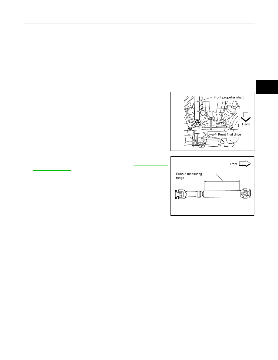
PROPELLER SHAFT VIBRATION

If a vibration is present at high speed, inspect the propeller shaft runout first.
1. Measure the runout of the propeller shaft tube at several points

by rotating the final drive companion flange with your hands.

Refer to 

DLN-136, "General Specification"

.

2. If the runout exceeds specifications, disconnect the propeller

shaft at the final drive companion flange; then rotate the com-

panion flange 90

°, 180° and 270° and reconnect the propeller

shaft.

3. Check the runout again. If the runout still exceeds specifications,

replace the propeller shaft assembly. Refer to 

DLN-136, "Gen-

eral Specification"

.

4. After installation, check for vibration by driving the vehicle. 

LDIA0160E

LDIA0118E

DLN-132

< UNIT REMOVAL AND INSTALLATION >

[PROPELLER SHAFT: 2F1310]

PROPELLER SHAFT

UNIT REMOVAL AND INSTALLATION

PROPELLER SHAFT

Removal and Installation

INFOID:0000000006179518

COMPONENTS

REMOVAL

1. Put matching marks on the front propeller shaft flange yoke and

the front final drive companion flange as shown.

CAUTION:

For matching marks, use paint. Never damage the flange

yoke and companion flange of the front final drive. 

2. Put matching marks on the front propeller shaft flange yoke and

the transfer companion flange.

CAUTION:

For matching marks, use paint. Never damage the flange

yoke and companion flange of the front final drive. 

3. Remove the bolts and then remove the front propeller shaft from

the front final drive and transfer. 

INSPECTION 

1.

Propeller shaft tube

2.

Snap ring

3.

Journal bearing

4.

Journal

5.

Flange yoke

Front

WDIA0304E

SDIA2046E

PROPELLER SHAFT

DLN-133

< UNIT REMOVAL AND INSTALLATION >

[PROPELLER SHAFT: 2F1310]

C

E

F

G

H

I

J

K

L

M

A

B

DLN

N

O

P

• Inspect the propeller shaft runout. If runout exceeds the limit,

replace the propeller shaft assembly. Refer to 

DLN-145, "General

Specification"

.

• While holding the flange yoke on one side, check axial play of the

joint as shown. If the journal axial play exceeds the specification,

repair or replace the journal parts. Refer to 

DLN-145, "General

Specification"

.

• Check the propeller shaft tube surface for dents or cracks. If dam-

age is detected, replace the propeller shaft assembly.

INSTALLATION

Installation is in the reverse order of removal.

• After installation, check for vibration by driving the vehicle. Refer to 

DLN-130, "NVH Troubleshooting Chart"

.

CAUTION:

Do not reuse the bolts and nuts. Always install new ones.

LDIA0118E

LDIA0117E

DLN-134

< UNIT DISASSEMBLY AND ASSEMBLY >

[PROPELLER SHAFT: 2F1310]

PROPELLER SHAFT

UNIT DISASSEMBLY AND ASSEMBLY

PROPELLER SHAFT

Disassembly and Assembly

INFOID:0000000006179519

DISASSEMBLY

Journal

1. Put matching marks on the front propeller shaft and flange yoke

as shown.

CAUTION:

For matching marks, use paint. Never damage the front pro-

peller shaft or flange yoke.

2. Remove the snap rings.

3. Push out and remove the journal bearings by lightly tapping the

flange yoke with a hammer, taking care not to damage the jour-

nal or flange yoke hole.

NOTE:

Put marks on the disassembled parts so that they can be rein-

stalled in their original positions from which they were removed.

4. Push out and remove the remaining journal bearings at the

opposite side by lightly tapping the flange yoke with a hammer,

taking care not to damage the journal or flange yoke hole.

NOTE:

Put marks on the disassembled parts so that they can be rein-

stalled in their original positions from which they were removed.

ASSEMBLY

SPD128

APD011

SPD732

SPD131


Content   ..  296  297  298  299   ..