Nissan Titan A60. Manual - part 291


  Index      Nissan     Nissan Titan A60 (2011 year) - Service and Repair Manual


Search            


Content   ..  289  290  291  292   ..


Nissan Titan A60. Manual - part 291


TRANSFER ASSEMBLY

DLN-103

< UNIT DISASSEMBLY AND ASSEMBLY >

[TRANSFER: TX15B]

C

E

F

G

H

I

J

K

L

M

A

B

DLN

N

O

P

UNIT DISASSEMBLY AND ASSEMBLY

TRANSFER ASSEMBLY

Disassembly and Assembly

INFOID:0000000006179508
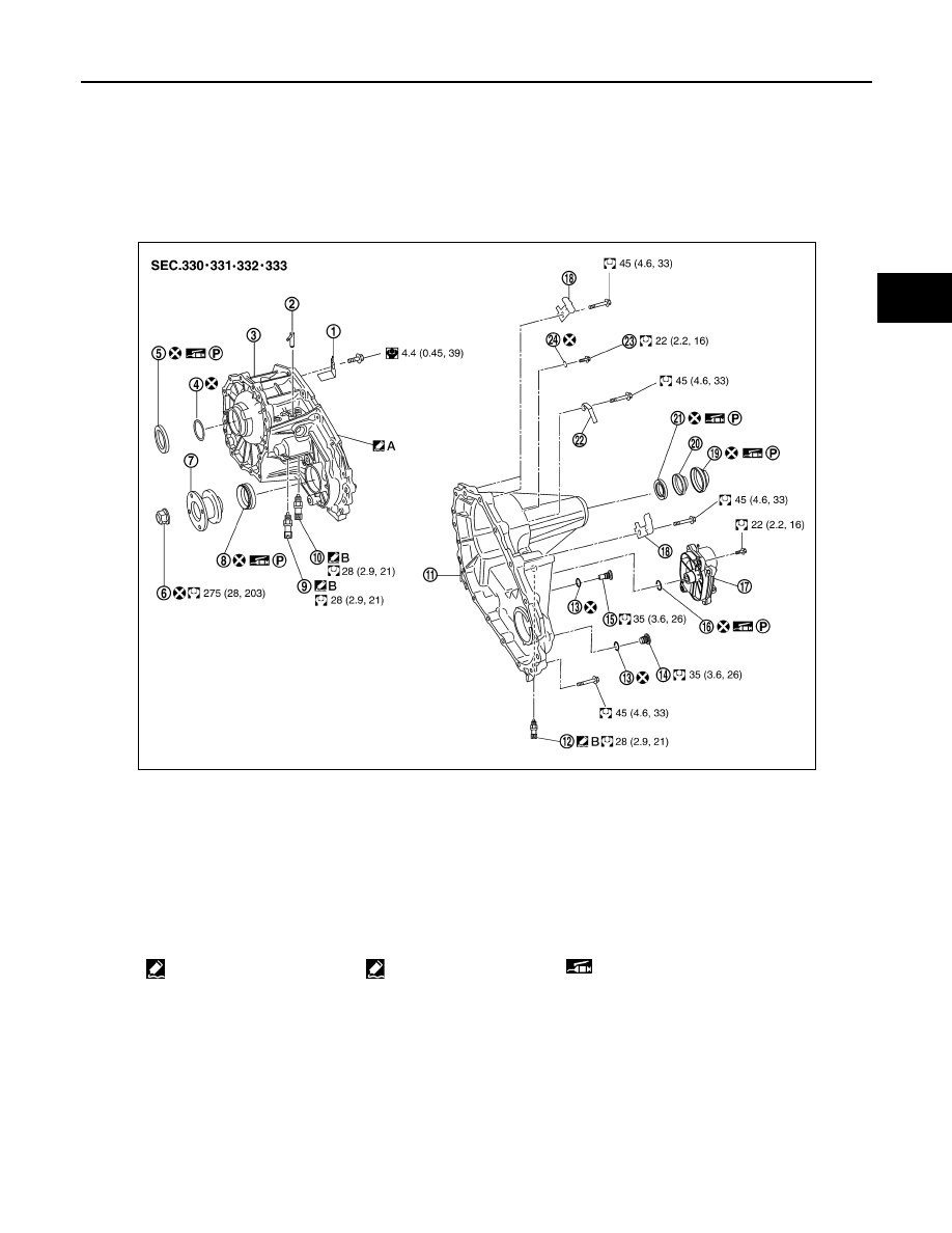
COMPONENTS

1.

Baffle plate

2.

Breather tube

3.

Front case

4.

Snap ring

5.

Input oil seal

6.

Self-lock nut

7.

Companion flange

8.

Front oil seal

9.

4LO switch (gray with green paint)

10. ATP switch (black)

11. Rear case

12. Wait detection switch (gray)

13. Gasket

14. Filler plug

15. Drain plug

16. O-ring

17. Transfer control device

18. Harness bracket

19. Dust cover

20. Oil cover

21. Rear oil seal

22. Air breather hose clamp

23. Retainer bolt

24. Gasket

A: Apply Genuine Anaerobic 
Liquid Gasket or equivalent.

B: Apply Genuine Silicone 
RTV or equivalent.

P: Apply petroleum jelly

AWDIA0749GB

DLN-104

< UNIT DISASSEMBLY AND ASSEMBLY >

[TRANSFER: TX15B]

TRANSFER ASSEMBLY

DISASSEMBLY

1. Remove the drain plug and filler plug.

1.

Input bearing

2.

Snap ring

3.

Internal gear

4.

Carrier bearing

5.

Sun gear

6.

Needle bearing

7.

Metal bushing

8.

Planetary carrier assembly

9.

L-H sleeve

10. Drive chain

11. Mainshaft

12. Sprocket

13. 2-4 sleeve

14. Clutch gear

15. Oil pump assembly

16. Retainer

17. Mainshaft rear bearing

18. Front bearing

19. Front drive shaft

20. Rear bearing

21. L-H shift fork

22. L-H shift rod

23. Retaining pin

24. 2-4 shift bracket

25. 2-4 shift fork

26. Fork guide collar

27. 2-4 shift fork spring

28. Retaining ring

29. Snap ring

30. Shift collar

31. Clevis pin

32. Drum cam

33. Control shift rod

34. Spacer

AWDIA0016GB

TRANSFER ASSEMBLY

DLN-105

< UNIT DISASSEMBLY AND ASSEMBLY >

[TRANSFER: TX15B]

C

E

F

G

H

I

J

K

L

M

A

B

DLN

N

O

P

2. Remove the transfer control device from the rear case.
3. Remove the O-ring from the transfer control device.

4. Remove the self-lock nut from the companion flange using suit-

able tool.

5. Put a matching mark on top of the front drive shaft in line with

the mark on the companion flange.

CAUTION:

Use paint to make the matching mark on the front drive

shaft. Do not damage the front drive shaft.

6.  Remove the companion flange using suitable tool.

7. Remove the front oil seal from the front case using Tool.

CAUTION:

Do not damage front case or front drive shaft.

SDIA2212E

SDIA2841E

SDIA2779E

WDIA0133E

Tool number

: ST33290001 (J-34286)

SDIA2423E

DLN-106

< UNIT DISASSEMBLY AND ASSEMBLY >

[TRANSFER: TX15B]

TRANSFER ASSEMBLY

8. Remove the 4LO switch [gray (with green paint)] and ATP switch

(black) from the front case.

9. Remove the wait detection switch (gray) from the rear case.

10. Remove the dust cover from the rear case using suitable tool.

CAUTION:

Do not damage rear case.

11. Remove the oil cover from the dust cover.
12. Remove the rear oil seal from the rear case using Tool.

CAUTION:

Do not damage rear case or mainshaft.

13. Remove the input oil seal from the front case using suitable tool.

CAUTION:

Do not damage front case, sun gear or input bearing.

PDIA0090E

PDIA0091E

Tool number

: ST33290001 (J-34286)

SDIA2424E

PDIA0094E


Content   ..  289  290  291  292   ..