Nissan Titan A60. Manual - part 270


  Index      Nissan     Nissan Titan A60 (2011 year) - Service and Repair Manual


Search            


Content   ..  268  269  270  271   ..


Nissan Titan A60. Manual - part 270


NOISE, VIBRATION AND HARSHNESS (NVH) TROUBLESHOOTING

DLN-19

< SYSTEM DESCRIPTION >

[TRANSFER: TX15B]

C

E

F

G

H

I

J

K

L

M

A

B

DLN

N

O

P

NOISE, VIBRATION AND HARSHNESS (NVH) TROUBLESHOOTING

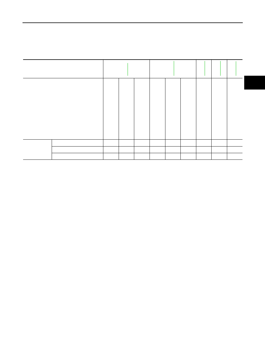
NVH Troubleshooting Chart

INFOID:0000000006179431

Use the chart below to help you find the cause of the symptom. The numbers indicate the order of the inspec-

tion. If necessary, repair or replace these parts.

Reference page

DLN-91

DLN-103

DLN-125

DLN-103

DLN-1

19

SUSPECTED PARTS
(Possible cause)

T

R

ANSFER F

LUID (Level

 low)

T

R

ANSFER F

LUID (W

rong)

T

R

ANSFER F

LUID (Level

 too high)

LI

QUI

D

 GASKET (Dam

ag

ed

)

O-RI

NG (W

orn

 or da

ma

ge

d)

OIL

 SEAL

 (W

orn

 or da

ma

ge

d)

S

H

IFT 

FO

RK

 (W

orn

 or d

am

a

ged

)

GEAR (W

orn

 o

r da

ma

ge

d)

B

EARING

 (W

orn

 or 

da

ma

ge

d)

Symptom

Noise

1

2

3

3

Transfer  fluid  leakage

3

1

2

2

2

Hard to shift or will not shift

1

1

2

DLN-20

< DTC/CIRCUIT DIAGNOSIS >

[TRANSFER: TX15B]

P1801, P1811 POWER SUPPLY CIRCUIT FOR TRANSFER CONTROL UNIT

DTC/CIRCUIT DIAGNOSIS

P1801, P1811 POWER SUPPLY CIRCUIT FOR TRANSFER CONTROL
UNIT

Description

INFOID:0000000006179432

The transfer control unit controls the transfer control device which controls shifts between 4H and 4LO and

between 2WD and 4WD.  When the vehicle battery is removed, the power supply to the transfer control unit is

interrupted, and self-diagnosis memory function is suspended.  DTCs P1801, P1811 or flash code 8 may also

set when the power supply voltage for the transfer control unit is abnormally low while driving.

DTC Logic

INFOID:0000000006179433

DTC DETECTION LOGIC

DTC CONFIRMATION PROCEDURE

1.

DTC CONFIRMATION PROCEDURE

1. Turn ignition switch ON.

2. Perform self-diagnosis.
Are DTCs P1801, P1811 or flash code 8 detected?

YES

>> Perform diagnosis procedure. Refer to 

DLN-20, "Diagnosis Procedure"

.

NO

>> Inspection End.

Diagnosis Procedure

INFOID:0000000006179434

Regarding Wiring Diagram information, refer to 

DLN-62, "Wiring Diagram"

.

1.

CHECK POWER SUPPLY

1. Turn ignition switch OFF.  (Stay for at least 5 seconds.)

2. Disconnect transfer control unit harness connector.

3. Check voltage between transfer control unit harness connector

terminals and ground.

DTC

CONSULT-III

Diagnostic item is detected when...

Reference

[P1801]

*INITIAL START*

Due to removal of battery which cuts off 
power supply to transfer control unit, 
self-diagnosis memory function is sus-
pended.

DLN-20, "Diagnosis Procedure"

[P1811]

BATTERY VOLTAGE

Power supply voltage for transfer control 
unit is abnormally low while driving.

Connector

Terminal

Voltage (Approx.)

E142

19 - Ground

Battery voltage

25 - Ground

0V

E143

40 - Ground

Battery voltage

44 - Ground

0V

45 - Ground

SDIA3360E

P1801, P1811 POWER SUPPLY CIRCUIT FOR TRANSFER CONTROL UNIT

DLN-21

< DTC/CIRCUIT DIAGNOSIS >

[TRANSFER: TX15B]

C

E

F

G

H

I

J

K

L

M

A

B

DLN

N

O

P

4. Turn ignition switch ON. (Do not start engine.)

5. Check voltage between transfer control unit harness connector

terminals and ground.

OK or NG

OK

>> GO TO 2.

NG

>> Check the following. If any items are damaged, repair or replace damaged parts.

• 10A fuses [No. 26 located in the fuse and fusible link box or 59 located in the fuse and relay box]

• 20A fuse [No. 53, located in the IPDM E/R]

• Harness for short or open between battery and transfer control unit harness connector E142 ter-

minal 19.

• Harness for short or open between battery and transfer shut off relay 2 harness connector E47

terminal 1 and 5.

• Harness for short or open between battery and transfer shut off relay 1 harness connector E46

terminal 5.

• Harness for short or open between ignition switch and transfer control unit harness connector

E142 terminal 25.

• Harness for short or open between ignition switch and transfer shut off relay 1 harness connec-

tor E46 terminal 2.

• Harness for short or open between transfer shut off relay 2 harness connector E47 terminal 3

and transfer control unit harness connector E143 terminals 44, 45.

• Harness for short or open between transfer shut off relay 1 harness connector E46 terminal 3

and transfer control unit harness connector E143 terminals 44, 45.

• Harness for short or open between transfer shut off relay 2 harness connector E47 terminal 2

and transfer control unit harness connector E143 terminal 40.

• Harness for open between transfer shut off relay 1 harness connector E46 terminal 1 and

ground.

• Battery and ignition switch.

• Transfer shut off relay 1, 2. Refer to COMPONENT INSPECTION .

2.

CHECK GROUND CIRCUIT

1. Turn ignition switch OFF.

2. Disconnect transfer control unit harness connector.

3. Check continuity between transfer control unit harness connec-

tor E142 terminals 6 and 18, and E143 terminal 32 and ground.

Also check harness for short to power.

OK or NG

OK

>> GO TO 3.

NG

>> Repair open circuit or short to power in harness or con-

nectors.

3.

CHECK TRANSFER CONTROL UNIT

Check transfer control unit input/output signal. Refer to 

DLN-55, "Reference Value"

.

OK or NG

OK

>> GO TO 4.

NG

>> Check transfer control unit pin terminals for damage or loose connection with harness connector.

If any items are damaged, repair or replace damaged parts.

Connector

Terminal

Voltage (Approx.)

E142

19 - Ground

Battery voltage

25 - Ground

E143

40 - Ground

44 - Ground

45 - Ground

SDIA3361E

Continuity should exist.

SDIA3362E

DLN-22

< DTC/CIRCUIT DIAGNOSIS >

[TRANSFER: TX15B]

P1801, P1811 POWER SUPPLY CIRCUIT FOR TRANSFER CONTROL UNIT

4.

CHECK DTC

Perform the self-diagnosis, after driving a vehicle for a while.
OK or NG

OK

>> Inspection End.

NG

>> Replace transfer control unit.  Refer to 

DLN-93, "Removal and Installation"

.

Component Inspection

INFOID:0000000006179435

1. Turn ignition switch OFF.  (Stay for at least 5 seconds.)
2. Remove transfer shut off relay 1 and transfer shut off relay 2. Refer to 

DLN-12, "Component Parts Loca-

tion"

.

3. Apply 12V direct current between transfer shut off relay termi-

nals 1 and 2.

4. Check continuity between relay terminals 3 and 5.

5. If inspection results are not normal, replace the transfer shut off

relay 1 or 2.

Condition

Continuity

12V direct current supply between terminals 1 and 2

Yes

OFF

No

SCIA1245E


Content   ..  268  269  270  271   ..