Nissan Titan A60. Manual - part 271


  Index      Nissan     Nissan Titan A60 (2011 year) - Service and Repair Manual


Search            


Content   ..  269  270  271  272   ..


Nissan Titan A60. Manual - part 271


P1802 – P1804, P1809 TRANSFER CONTROL UNIT

DLN-23

< DTC/CIRCUIT DIAGNOSIS >

[TRANSFER: TX15B]

C

E

F

G

H

I

J

K

L

M

A

B

DLN

N

O

P

P1802 – P1804, P1809 TRANSFER CONTROL UNIT

Description

INFOID:0000000006179436

The transfer control unit controls the transfer control device which controls shifts between 4H and 4LO and

between 2WD and 4WD.  DTC P1802 - P1804 or P1809 may set when any of the following occur:

• Malfunction is detected in the memory (RAM) system of transfer control unit.

• Malfunction is detected in the memory (ROM) system of transfer control unit.

• Malfunction is detected in the memory (EEPROM) system of transfer control unit.

• AD converter system of transfer control unit is malfunctioning.

Flash code 5 may set when the following occurs:

• AD converter system of transfer control unit is malfunctioning.

DTC Logic

INFOID:0000000006179437

DTC DETECTION LOGIC

DTC CONFIRMATION PROCEDURE

1.

DTC CONFIRMATION PROCEDURE

1. Turn ignition switch ON.

2. Perform self-diagnosis.
Are DTCs P1802 - P1804, P1809 or flash code 5 detected?

YES

>> Perform diagnosis procedure. Refer to 

DLN-23, "Diagnosis Procedure"

.

NO

>> Inspection End.

Diagnosis Procedure

INFOID:0000000006179438

1.

INSPECTION START

Do you have CONSULT-III?
YES or NO

YES

>> GO TO 2.

NO

>> GO TO 3.

2.

PERFORM SELF-DIAGNOSIS (WITH CONSULT-III)

1. Turn ignition switch ON.

2. Select SELF-DIAG RESULTS mode for ALL MODE AWD/4WD with CONSULT-III.

3. Touch ERASE.

4. Turn ignition switch OFF and wait at least 10 seconds.

5. Perform the self-diagnosis again.
Is the CONTROL UNIT 1 [P1802], CONTROL UNIT 2 [P1803], CONTROL UNIT 3 [P1804] or CONTROL

UNIT 4 [P1809] displayed?

YES

>> Replace transfer control unit. Refer to 

DLN-93, "Removal and Installation"

.

NO

>> Inspection End.

3.

PERFORM SELF-DIAGNOSIS (WITHOUT CONSULT-III)

1. Perform the self-diagnosis and then erase self-diagnostic results.
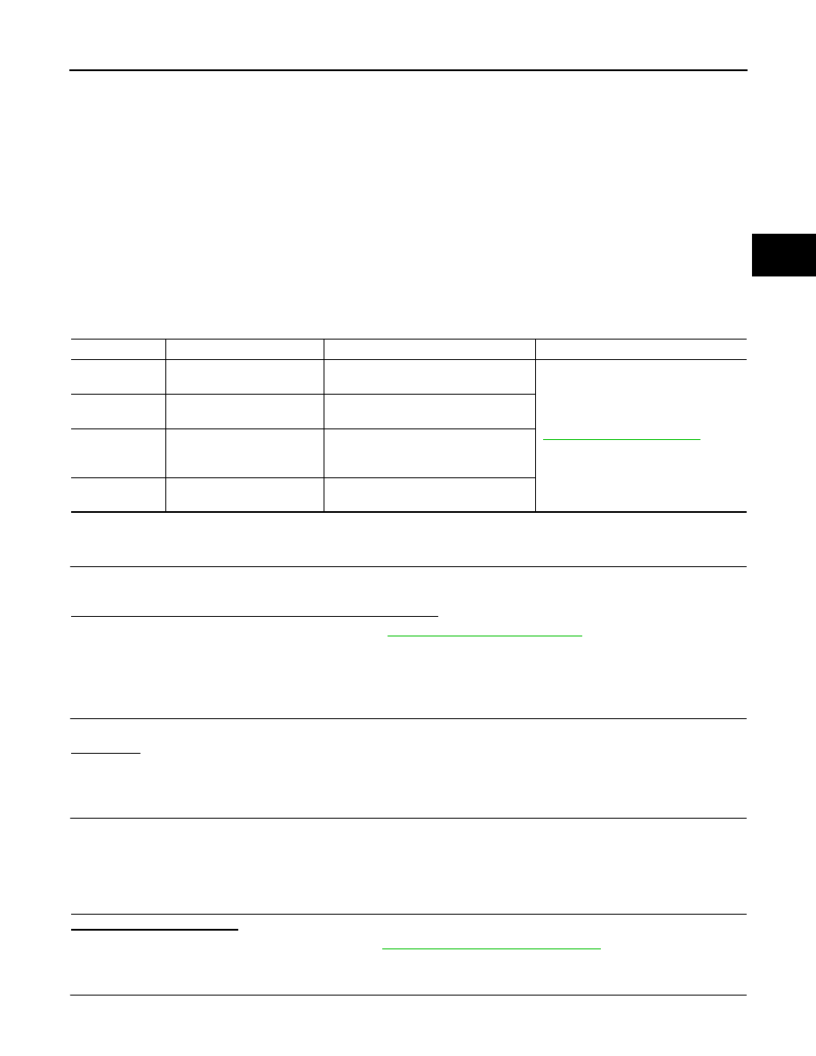
DTC

CONSULT-III

Diagnostic item is detected when...

Reference

[P1802]

CONTROL UNIT 1

Malfunction is detected in the memory 
(RAM) system of transfer control unit.

DLN-23, "Diagnosis Procedure"

[P1803]

CONTROL UNIT 2

Malfunction is detected in the memory 
(ROM) system of transfer control unit.

[P1804]

CONTROL UNIT 3

Malfunction is detected in the memory 
(EEPROM) system of transfer control 
unit.

[P1809]

CONTROL UNIT 4

AD converter system of transfer control 
unit is malfunctioning.

DLN-24

< DTC/CIRCUIT DIAGNOSIS >

[TRANSFER: TX15B]

P1802 – P1804, P1809 TRANSFER CONTROL UNIT

2. Perform the self-diagnosis again.
Do the self-diagnostic results indicate AD converter?

YES

>> Replace transfer control unit. Refer to 

DLN-93, "Removal and Installation"

.

NO

>> Inspection End.

P1807 VEHICLE SPEED SENSOR (A/T)

DLN-25

< DTC/CIRCUIT DIAGNOSIS >

[TRANSFER: TX15B]

C

E

F

G

H

I

J

K

L

M

A

B

DLN

N

O

P

P1807 VEHICLE SPEED SENSOR (A/T)

Description

INFOID:0000000006179439

The transmission control module (TCM) transmits the output shaft revolution signal via CAN communication to

Transfer control unit.  DTC P1807 or flash code 2 will set when a malfunction is detected in the output shaft

revolution signal or an improper signal is input while driving.

DTC Logic

INFOID:0000000006179440

DTC DETECTION LOGIC

DTC CONFIRMATION PROCEDURE

1.

DTC CONFIRMATION PROCEDURE

1. Turn ignition switch ON.

2. Perform self-diagnosis.
Is DTC P1807 or flash code 2 detected?

YES

>> Perform diagnosis procedure. Refer to 

DLN-25, "Diagnosis Procedure"

.

NO

>> Inspection End.

Diagnosis Procedure

INFOID:0000000006179441

1.

CHECK DTC WITH TCM

Perform self-diagnosis with TCM. Refer to 

TM-36, "CONSULT-III Function (TRANSMISSION)"

.

Is any malfunction detected by self-diagnosis?

YES

>> Check the malfunctioning system.

NO

>> GO TO 2.

2.

CHECK TRANSFER CONTROL UNIT

Check transfer control unit input/output signal. Refer to 

DLN-55, "Reference Value"

.

Are the inspection results normal?

YES

>> GO TO 3.

NO

>> Check transfer control unit pin terminals for damage or loose connection with harness connector.

If any items are damaged, repair or replace damaged parts.

3.

CHECK DTC

Drive vehicle and then perform Self-diagnosis.
Is DTC P1807 displayed?

YES

>> Perform self-diagnosis with TCM again.

NO

>> Inspection End.

DTC

CONSULT-III

Diagnostic item is detected when...

Reference

[P1807]

VHCL SPEED SEN·AT

• Malfunction is detected in output shaft 

revolution signalthat is output from 
TCM through CAN communication.

• Improper signal is input while driving.

DLN-25, "Diagnosis Procedure"

DLN-26

< DTC/CIRCUIT DIAGNOSIS >

[TRANSFER: TX15B]

P1808 VEHICLE SPEED SENSOR (ABS)

P1808 VEHICLE SPEED SENSOR (ABS)

Description

INFOID:0000000006179442

The ABS actuator and electric unit (control unit) transmits a vehicle speed signal via CAN communication to

the transfer control unit.  DTC P1808 or flash code 3 sets when a malfunction is detected in the vehicle speed

signal that is output from the ABS actuator and electric unit (control unit) or an improper signal is input while

driving.

DTC Logic

INFOID:0000000006179443

DTC DETECTION LOGIC

DTC CONFIRMATION PROCEDURE

1.

DTC CONFIRMATION PROCEDURE

1. Turn ignition switch ON.

2. Perform self-diagnosis.
Is DTC P1808 or flash code 3 displayed?

YES

>> Perform diagnosis procedure. Refer to 

DLN-26, "Diagnosis Procedure"

.

NO

>> Inspection End.

Diagnosis Procedure

INFOID:0000000006179444

1.

CHECK DTC WITH ABS ACTUATOR AND ELECTRIC UNIT (CONTROL UNIT)

Perform self-diagnosis with ABS actuator and electric unit (control unit). Refer to 

BRC-24, "CONSULT-III

Function (ABS)"

.

Is any malfunction detected by self-diagnosis?

YES

>> Check the malfunctioning system.

NO

>> GO TO 2.

2.

CHECK TRANSFER CONTROL UNIT

Check transfer control unit input/output signal. Refer to 

DLN-55, "Reference Value"

.

Are the inspection results normal?

YES

>> GO TO 3.

NO

>> Check transfer control unit pin terminals for damage or loose connection with harness connector.

If any items are damaged, repair or replace damaged parts.

3.

CHECK DTC

Drive vehicle and then perform Self-diagnosis.
Is DTC P1808 displayed?

YES

>> Perform self-diagnosis with ABS actuator and electric unit (control unit).

NO

>> Inspection End.

DTC

CONSULT-III

Diagnostic item is detected when...

Reference

[P1808]

VHCL SPEED SEN·ABS

• Malfunction is detected in vehicle 

speed signal that is output from ABS 
actuator and electric unit (control unit) 
through CAN communication.

• Improper signal is input while driving.

DLN-26, "Diagnosis Procedure"


Content   ..  269  270  271  272   ..