Nissan Titan A60. Manual - part 192


  Index      Nissan     Nissan Titan A60 (2011 year) - Service and Repair Manual


Search            


Content   ..  190  191  192  193   ..


Nissan Titan A60. Manual - part 192


BODY CONSTRUCTION

BRM-27

< UNIT REMOVAL AND INSTALLATION >

C

D

E

F

G

H

I

J

L

M

A

B

BRM

N

O

P

4. Disconnect the fuel filler neck from the bed side outer.
5. Remove the rear bumper assembly.
6. Remove the pick-up bed assembly.

Installation

Installation is in the reverse order of removal.

• Shim as necessary for proper fit and finish.

Foam Repair

INFOID:0000000006158471

During factory body assembly, foam insulators are installed in certain body panels and locations around the

vehicle. Use the following procedure(s) to replace any factory-installed foam insulators.

URETHANE FOAM APPLICATIONS

Use commercially available spray foam for sealant (foam material) repair of material used on vehicle. Read

instructions on product for fill procedures.

FILL PROCEDURES

1. Fill procedures after installation of service part.

-

Remove foam material remaining on vehicle side.

-

Clean area in which foam was removed.

-

Install service part.

-

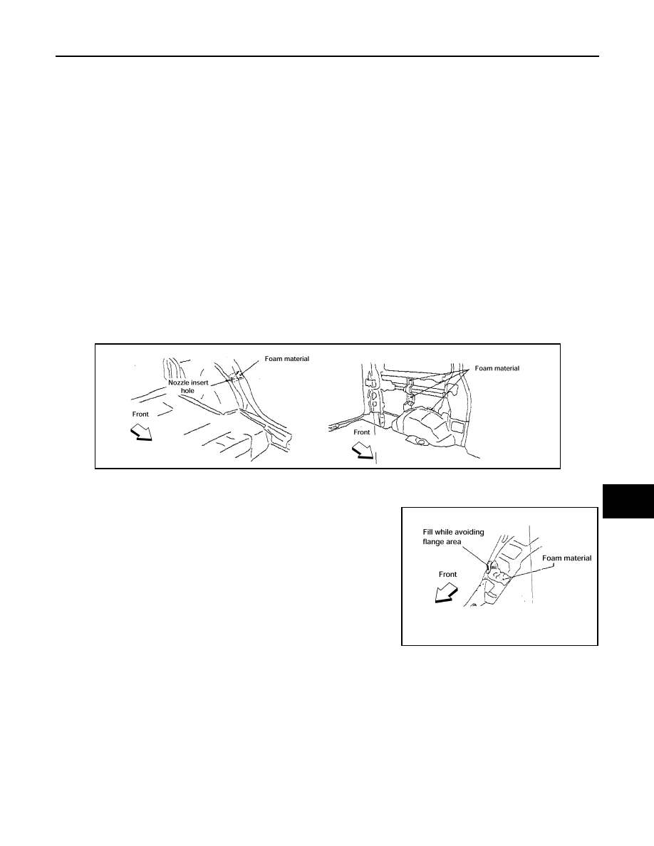
Insert nozzle into hole near fill area and fill foam material or fill in enough to close gap with the service

part.

2. Fill procedures before installation of service part.

-

Remove foam material remaining on vehicle side.

-

Clean area in which foam was removed.

-

Fill foam material on wheelhouse outer side.

NOTE:

Fill in enough to close gap with service part while avoiding flange

area.

-

Install service part.

NOTE:

Refer to label for information on working times.

LIIA1081E

LIIA1082E

BRM-28

< UNIT REMOVAL AND INSTALLATION >

BODY ALIGNMENT

BODY ALIGNMENT

Body Alignment

INFOID:0000000006158472

BODY CENTER MARKS

A mark has been placed on each part of the body to indicate the vehicle center. When repairing parts dam-

aged by an accident which might affect the vehicle frame (members, pillars, etc.), more accurate and effective

repair will be possible by using these marks together with body alignment specifications.

ALKIA0502GB

BODY ALIGNMENT

BRM-29

< UNIT REMOVAL AND INSTALLATION >

C

D

E

F

G

H

I

J

L

M

A

B

BRM

N

O

P

PANEL PARTS MATCHING MARKS

A mark has been placed on each body panel to indicate the parts matching positions. When repairing parts

damaged by an accident which might affect the vehicle structure (members, pillars, etc.), more accurate and

effective repair will be possible by using these marks together with body alignment specifications.

DESCRIPTION

• All dimensions indicated in the figures are actual.

• When using a tracking gauge, adjust both pointers to equal length. Then check the pointers and gauge itself

to make sure there is no free play.

WIIA0338E

BRM-30

< UNIT REMOVAL AND INSTALLATION >

BODY ALIGNMENT

• When a measuring tape is used, check to be sure there is no elongation, twisting or bending.

• Measurements should be taken at the center of the mounting holes.

• An asterisk (*) following the value at the measuring point indicates that the measuring point on the other side

is symmetrically the same value.

• The coordinates of the measurement points are the distances measured from the standard line of "X", "Y"

and "Z".

Engine Compartment

LIIA1506E


Content   ..  190  191  192  193   ..