Nissan Titan A60. Manual - part 147
BRAKE PEDAL
BR-15
< PERIODIC MAINTENANCE >
C
D
E
G
H
I
J
K
L
M
A
B
BR
N
O
P
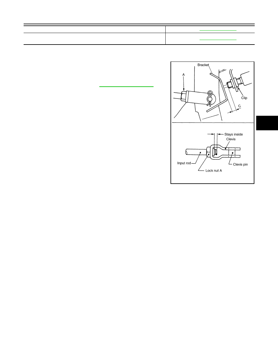
ADJUSTMENT
1. Loosen the stop lamp switch and ASCD cancel switch by turning them 45
° counterclockwise.
2. Loosen lock nut (A) on the input rod, then turn input rod to adjust
the brake pedal to the specified height. When finished adjusting,
tighten the lock nut (A) to specification.
CAUTION:
Make sure that the screw portion of the end of input rod is
located inside the clevis.
3. With the brake pedal pulled up and held by hand, press the stop
lamp switch and the ASCD cancel switch in until the threaded
ends contact the brake pedal bracket.
4. With the threaded ends of the stop lamp switch and ASCD can-
cel switch contacting the pedal bracket, turn the switches 45
°
clockwise to lock in place. Check that the stop lamp switch and
ASCD cancel switch threaded end to brake pedal bracket gap
(C) is within specifications.
CAUTION:
Make sure that the gap (C) between the brake pedal bracket
and stop lamp switch and ASCD cancel switch threaded
ends are within specification.
5. Check the brake pedal for smooth operation.
CAUTION:
Make sure that the stop lamp goes off when the brake pedal
is released.
Pedal full stroke (T)
Clearance between brake pedal bracket and threaded end of stop lamp switch and
ASCD cancel switch
Lock nut (A)
: Refer to
PFIA0436E