Nissan Titan A60. Manual - part 70


  Index      Nissan     Nissan Titan A60 (2011 year) - Service and Repair Manual


Search            


Content   ..  68  69  70  71   ..


Nissan Titan A60. Manual - part 70


AV

DIAGNOSIS SYSTEM (AUDIO UNIT)

AV-105

< SYSTEM DESCRIPTION >

[PREMIUM WITHOUT NAVIGATION]

C

D

E

F

G

H

I

J

K

L

M

B

A

O

P

DIAGNOSIS SYSTEM (AUDIO UNIT)

AV SWITCH
AV SWITCH : Component Function Check

INFOID:0000000006166497

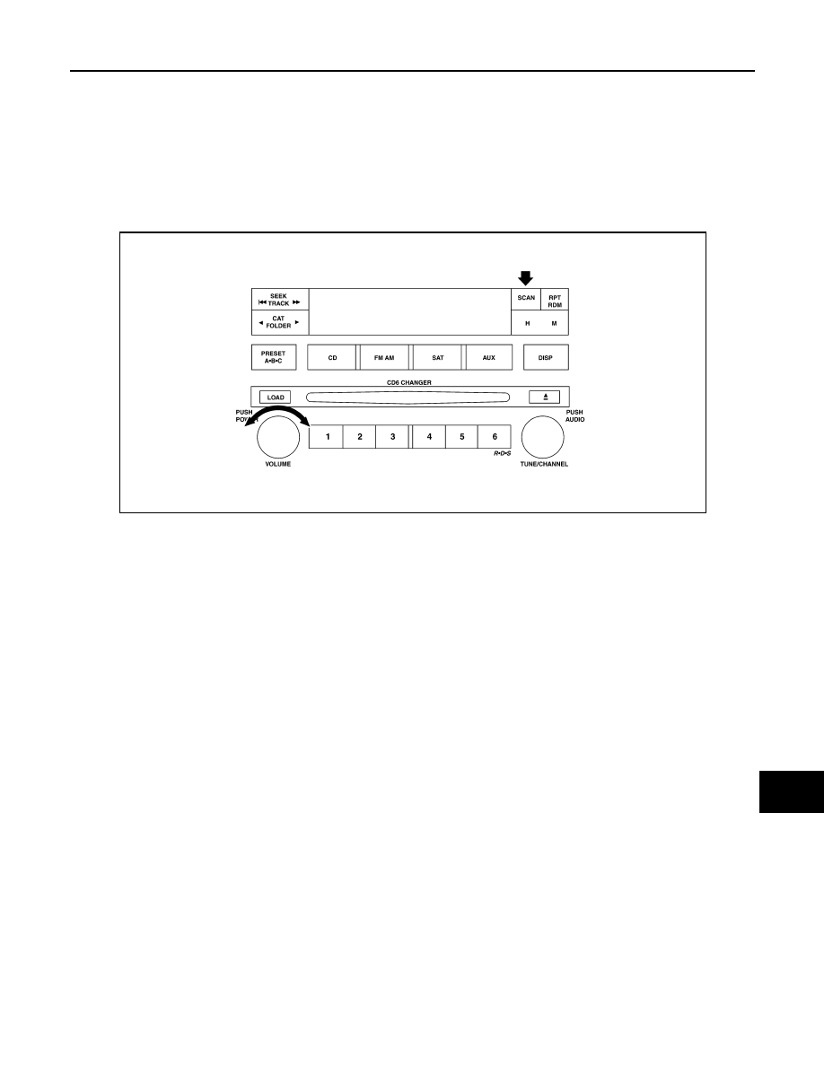
STARTING THE SELF-DIAGNOSIS MODE

1. Turn ignition switch from OFF to ACC.

2. Press and hold the “SCAN” switch and turn the volume control dial clockwise or counterclockwise for 30

clicks or more.

Then the self-diagnosis operates. A single beep indicates self-diagnosis mode is active.

3. Initially, all display segments will be illuminated.

4. Press each switch. When each switch is pressed, its name and communication code will be displayed

NOTE:

CD player LOAD and EJECT buttons are not included in this test and will not change the display when

pressed.

DIAGNOSIS FUNCTION 

• It can check for continuity of the switches by sounding the beep when each AV switch and steering switch is

pressed.

• It can check for continuity of harness between AV switch and steering switch.

EXITING THE SELF-DIAGNOSIS MODE

Turn ignition switch OFF. Then the self-diagnosis ends.

WKIA4645E

AV-106

< SYSTEM DESCRIPTION >

[PREMIUM WITHOUT NAVIGATION]

DIAGNOSIS SYSTEM (BLUETOOTH CONTROL UNIT)

DIAGNOSIS SYSTEM (BLUETOOTH CONTROL UNIT)

Diagnosis Description

INFOID:0000000006166498

The Bluetooth control unit has two diagnostic checks. The first diagnostic check is performed automatically

every ignition cycle during control unit initialization. The second diagnostic check is performed by the techni-

cian using the steering wheel audio control switches prior to trouble diagnosis.

BLUETOOTH CONTROL UNIT INITIALIZATION CHECKS

• Internal control unit failure

• Bluetooth antenna connection open or shorted
• Steering wheel audio control switches [SEND(

)/END( )] stuck closed

• Vehicle speed pulse count

• Microphone connection test (with playback to operator)

• Bluetooth inquiry check

OPERATION PROCEDURE

1. Turn ignition switch to ACC or ON.

2. Wait for the Bluetooth system to complete initialization. This may take up to 10 seconds.
3. Press and hold the steering wheel audio control switch 

button for at least 5 seconds. The Bluetooth system will begin to

play a verbal prompt.

4. While the prompt is playing, press and hold the steering wheel

audio control switch   button until you hear the “Diagnostics

mode” prompt. The Bluetooth system will sound a 5 second

beep.

5. While the beep is sounding, press and hold the steering wheel

audio control switch   button again until you hear prompts.

6. The Bluetooth system has now entered into the diagnostic

mode. Results of the diagnostic checks will be verbalized to the

technician. Refer to 

AV-106, "Work Flow"

.

7. After the failure records are reported, an interactive microphone

test will be performed. Follow the voice prompt. If the micro-

phone test fails refer to 

AV-106, "Work Flow"

.

8. Self-diagnosis mode is complete when the voice prompt says “All diagnostic functions completed”.

Work Flow

INFOID:0000000006166499

ALNIA0448GB

ALNIA0449GB

Failure Message

Action

“Internal failure”

Replace Bluetooth control unit. Refer to 

AV-190, "Removal and Installation"

.

“Bluetooth antenna open”

1.

Inspect harness connection.

2.

Replace Bluetooth antenna. Refer to 

AV-189, "Removal and Installation"

.

“Bluetooth antenna shorted”

“Phone/Send for Hands Free System is stuck”

Check steering wheel audio control switches. Refer to 

AV-131, "Description"

.

“Phone/End for the Hands Free System is stuck”

“Microphone test” (failed interactive test)

1.

Inspect harness between Bluetooth control unit and microphone.

2.

Replace microphone. Refer to 

AV-188, "Removal and Installation"

.

AV

POWER SUPPLY AND GROUND CIRCUIT

AV-107

< DTC/CIRCUIT DIAGNOSIS >

[PREMIUM WITHOUT NAVIGATION]

C

D

E

F

G

H

I

J

K

L

M

B

A

O

P

DTC/CIRCUIT DIAGNOSIS

POWER SUPPLY AND GROUND CIRCUIT

AUDIO UNIT
AUDIO UNIT : Diagnosis Procedure

INFOID:0000000006166500

Regarding Wiring Diagram information, refer to 

AV-151, "Wiring Diagram - Without Navigation System"

.

1.

CHECK FUSES

Check that the following fuses of the audio unit are not are not blown.

Are the fuses OK?

YES

>> GO TO 2.

NO

>> If fuse is blown, be sure to eliminate cause of malfunction before installing new fuse.

2.

POWER SUPPLY CIRCUIT CHECK

1. Disconnect audio unit connector M171. 

2. Check voltage between the audio unit connector M171 and

ground.

Are the voltage results as specified?

YES

>> GO TO 3.

NO

>> • Check connector housing for disconnected or loose terminals.

• Repair harness or connector.

3.

GROUND CIRCUIT CHECK

Inspect audio unit case ground.
Does case ground pass inspection?

YES

>> Inspection End.

NO

>> Repair audio unit case ground.

AV SWITCH
AV SWITCH : Diagnosis Procedure

INFOID:0000000006166501

Regarding Wiring Diagram information, refer to 

AV-151, "Wiring Diagram - Without Navigation System"

.

1.

CHECK FUSE

Check that the fuses for the AV switch are not blown.

Unit

Terminals

Signal name

Fuse No.

Audio unit

6

Battery power

31

10

Ignition switch ACC or ON

4

(+)

(-)

OFF

ACC

ON

Connector

Terminal

M171

6

Ground

0V

Battery 
voltage

Battery 
voltage

10

Ground

Battery 
voltage

Battery 
voltage

Battery 
voltage

ALNIA0695GB

AV-108

< DTC/CIRCUIT DIAGNOSIS >

[PREMIUM WITHOUT NAVIGATION]

POWER SUPPLY AND GROUND CIRCUIT

Are the fuses OK?

YES

>> GO TO 2.

NO

>> If fuse is blown, be sure to eliminate cause of malfunction before installing new fuse.

2.

POWER SUPPLY CIRCUIT CHECK

1. Disconnect AV switch connector M98. 

2. Check voltage between the AV switch connector M98 and

ground.

Are the voltage results as specified?

YES

>> GO TO 3.

NO

>> • Check connector housings for disconnected or loose terminals.

• Repair harness or connector.

3.

GROUND CIRCUIT CHECK

1. Turn ignition switch OFF.

2. Check continuity between AV switch harness connector M98

and ground.

Are the continuity results as specified?

YES

>> Inspection End.

NO

>> Repair harness or ground.

SATELLITE RADIO TUNER
SATELLITE RADIO TUNER : Diagnosis Procedure

INFOID:0000000006166502

Regarding Wiring Diagram information, refer to 

AV-151, "Wiring Diagram - Without Navigation System"

.

1.

CHECK FUSES

Check that the following fuses of the satellite radio tuner (factory installed) are not blown.

Are the fuses OK?

YES

>> GO TO 2.

NO

>> If fuse is blown, be sure to eliminate cause of malfunction before installing new fuse.

Unit

Terminal

Signal name

Fuse No.

AV switch

1

Battery

31

2

Ignition switch ACC or ON

4

(+)

(-)

OFF

ACC

ON

Connector

Terminal

M98

1

Ground

Battery 
voltage

Battery 
voltage

Battery 
voltage

2

Ground

0V

Battery 
voltage

Battery 
voltage

ALNIA0696GB

Connector

Terminal

Continuity

M98

5

Ground

Yes

ALNIA0697GB

Unit

Terminals

Signal name

Fuse No.

Satellite radio tuner (factory in-
stalled)

32

Battery power

31

36

Ignition switch ACC or ON

4


Content   ..  68  69  70  71   ..