Nissan Titan A60. Manual - part 42
AP-6
< DTC/CIRCUIT DIAGNOSIS >
ADJUSTABLE PEDAL SYSTEM
DTC/CIRCUIT DIAGNOSIS
ADJUSTABLE PEDAL SYSTEM
Pedal Adjusting Switch Power Supply and Ground Circuit Inspection
INFOID:0000000006163397
Regarding Wiring Diagram information, refer to
.
1.
CHECK PEDAL ADJUSTING SWITCH POWER SUPPLY
1. Turn ignition switch OFF.
2. Disconnect pedal adjusting switch.
3. Check voltage between pedal adjusting switch connector M83
terminal 1 and ground.
Is inspection result normal?
YES
>> GO TO 2
NO
>> Repair or replace harness.
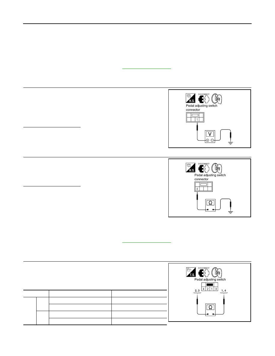
2.
CHECK PEDAL ADJUSTING SWITCH GROUND CIRCUIT
Check continuity between pedal adjusting switch connector M83 ter-
minal 4 and ground.
Is inspection result normal?
YES
>> Pedal adjusting switch power supply and ground circuit
is OK.
NO
>> Repair or replace harness.
Pedal Adjusting Motor Circuit Inspection
INFOID:0000000006163398
Regarding Wiring Diagram information, refer to
.
1.
CHECK PEDAL ADJUSTING SWITCH
1. Turn ignition switch OFF.
2. Disconnect pedal adjusting switch.
3. Check continuity between pedal adjusting switch terminals as
follows.
1 - Ground
: Battery voltage.
LIIA0894E
4 - Ground
: Continuity should exist.
LIIA0896E
Terminals
Condition
Continuity
3
1
Pedal adjusting switch forward.
Continuity should exist.
Pedal adjusting switch neutral.
Continuity should not exist.
4
Pedal adjusting switch backward.
Continuity should exist.
Pedal adjusting switch neutral.
Continuity should not exist.
LIIA0897E