Nissan Titan A60. Manual - part 25
ADP-90
< DTC/CIRCUIT DIAGNOSIS >
MIRROR SENSOR
1. Turn ignition switch OFF.
2. Disconnect automatic drive positioner control unit and door mir-
ror LH connector.
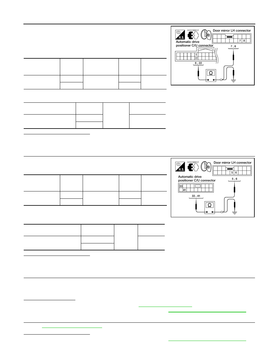
3. Check continuity between automatic drive positioner control unit
harness connector and door mirror LH harness connector.
4. Check continuity between automatic drive positioner control unit harness connector and ground.
Is the inspection result normal?
YES
>> GO TO 3.
NO
>> Repair or replace harness.
3.
CHECK DOOR MIRROR LH SENSOR CIRCUIT 2
1. Check continuity between automatic drive positioner control unit
harness connector and door mirror LH harness connector.
2. Check continuity between automatic drive positioner control unit
harness connector and ground.
Is the inspection result normal?
YES
>> GO TO 4.
NO
>> Repair or replace harness.
4.
CHECK PEDAL ADJUSTING OPERATION
1. Connect driver seat control unit connector and door mirror LH connector.
2. Turn ignition switch ON.
3. Check pedal adjusting operation with memory function.
Is the operation normal?
YES
>> Replace door mirror actuator LH. Refer to
NO
>> Replace automatic drive positioner control unit. Refer to
ADP-149, "Removal and Installation"
5.
CHECK INTERMITTENT INCIDENT
GI-39, "Intermittent Incident"
Is the inspection result normal?
YES
>> Replace automatic drive positioner control unit. Refer to
ADP-149, "Removal and Installation"
NO
>> Repair or replace the malfunctioning part.
Automatic drive
positioner control
unit connector
Terminal
Door mirror LH
connector
Terminal
Continuity
M33
6
D4
7
Yes
22
8
Automatic drive positioner
control unit connector
Terminal
Ground
Continuity
M33
6
No
22
LIIA1484E
Automatic drive
positioner control
unit connector
Terminal
Door mirror LH
connector
Terminal
Continuity
M34
33
D4
5
Yes
41
6
Automatic drive positioner
control unit connector
Terminal
Ground
Continuity
M34
33
No
41
LIIA1483E