Nissan Titan A60. Manual - part 23


  Index      Nissan     Nissan Titan A60 (2011 year) - Service and Repair Manual


Search            


Content   ..  21  22  23  24   ..


Nissan Titan A60. Manual - part 23


ADP-82

< DTC/CIRCUIT DIAGNOSIS >

RECLINING SENSOR

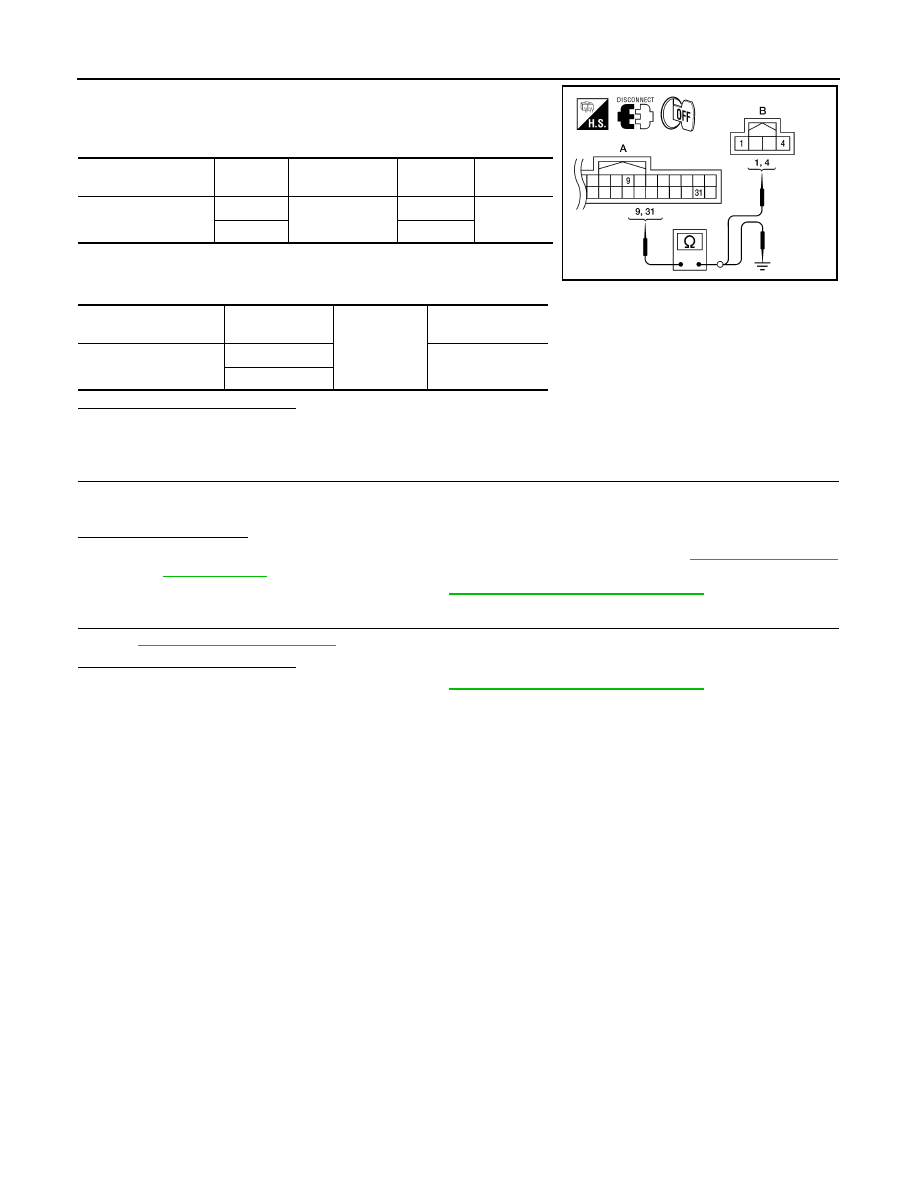
1. Disconnect driver seat control unit and reclining motor LH.

2. Check continuity between driver seat control unit harness con-

nector and reclining motor LH harness connector.

3. Check continuity between driver seat control unit harness con-

nector and ground.

Is the inspection result normal?

YES

>> GO TO 3

NO

>> Repair or replace harness.

3.

 CHECK SEAT OPERATION

1. Connect driver seat control unit and reclining motor LH connector.

2. Check seat operation (except reclining operation) with memory function.
Is the operation normal?

YES

>> Replace reclining motor LH. (Built in power seat frame assembly). Refer to 

SE-44, "Disassembly

and Assembly"

.

NO

>> Replace driver seat control unit. Refer to 

ADP-148, "Removal and Installation"

.

4.

 CHECK INTERMITTENT INCIDENT

Refer to 

GI-39, "Intermittent Incident"

.

Is the inspection result normal?

YES

>> Replace driver seat control unit. Refer to 

ADP-148, "Removal and Installation"

.

NO

>> Repair or replace the malfunctioning part.

Driver seat control 

unit connector

Terminal

Reclining motor 

connector

Terminal

Continuity

B202 (A)

9

B205 (B)

1

Yes

31

4

Driver seat control unit 

connector

Terminal

Ground

Continuity 

B202 (A)

9

No

31

ALJIA0318ZZ

LIFTING SENSOR (FRONT)

ADP-83

< DTC/CIRCUIT DIAGNOSIS >

C

D

E

F

G

H

I

K

L

M

A

B

ADP

N

O

P

LIFTING SENSOR (FRONT)

Description

INFOID:0000000006163538

• The lifting sensor (front) is installed to the power seat frame assembly.

• The pulse signal is input to the driver seat control unit when the lifting (front) is operated.

• The driver seat control unit counts the pulse and calculates the lifting (front) amount of the seat.

Component Function Check

INFOID:0000000006163539

1.

 CHECK FUNCTION

1. Select “LIFT FR PULSE” in “Data monitor” mode with CONSULT-III.

2. Check the lifting sensor (front) signal under the following conditions.

Is the indication normal?

YES

>> Inspection End.

NO

>> Perform diagnosis procedure. Refer to 

ADP-83, "Diagnosis Procedure"

.

Diagnosis Procedure

INFOID:0000000006163540

Regarding Wiring Diagram information, refer to 

ADP-128, "Wiring Diagram"

.

1.

 CHECK LIFTING SENSOR (FRONT) SIGNAL

1. Turn ignition switch OFF.

2. Read the voltage signal between driver seat control unit harness

connector and ground with an oscilloscope.

Is the inspection result normal?

YES

>> GO TO 4

NO

>> GO TO 2

2.

 CHECK LIFTING SENSOR (FRONT) CIRCUIT

Monitor item

Condition

Value

LIFT FR PULSE

Seat lifting (front)

Operate (up)

Change (increase)

Operate (down)

Change (decrease)

Release

No change

Terminals

Condition

Voltage signal

(+)

(–)

Driver 

seat con-

trol unit 

connector

Termi-

nal

B202

25

Ground

Seat 
lifting
(front)

Oper-
ate

Other 
than 
above

0 or 5

PIIA4561E

SIIA0691J

ADP-84

< DTC/CIRCUIT DIAGNOSIS >

LIFTING SENSOR (FRONT)

1. Disconnect driver seat control unit and lifting motor (front).

2. Check continuity between driver seat control unit harness con-

nector and lifting motor (front) harness connector.

3. Check continuity between driver seat control unit harness con-

nector and ground.

Is the inspection result normal?

YES

>> GO TO 3

NO

>> Repair or replace harness.

3.

 CHECK SEAT OPERATION

1. Connect driver seat control unit and lifting motor (front) connector.

2. Check seat operation [except lifting (front) operation] with memory function.
Is the operation normal?

YES

>> Replace lifting motor (front). (Built in power seat frame assembly). Refer to 

SE-44, "Disassembly

and Assembly"

.

NO

>> Replace driver seat control unit. Refer to 

ADP-148, "Removal and Installation"

.

4.

 CHECK INTERMITTENT INCIDENT

Refer to 

GI-39, "Intermittent Incident"

.

Is the inspection result normal?

YES

>> Replace driver seat control unit. Refer to 

ADP-148, "Removal and Installation"

.

NO

>> Repair or replace the malfunctioning part.

Driver seat control 

unit connector

Terminal

Lifting motor 

(front) connector

Terminal

Continuity

B202 (A)

16

B206 (B)

3

Yes

25

4

31

2

Driver seat control unit 

connector

Terminal

Ground

Continuity 

B202 (A)

16

No

25

31

ALJIA0319ZZ

LIFTING SENSOR (REAR)

ADP-85

< DTC/CIRCUIT DIAGNOSIS >

C

D

E

F

G

H

I

K

L

M

A

B

ADP

N

O

P

LIFTING SENSOR (REAR)

Description

INFOID:0000000006163541

• The lifting sensor (rear) is installed to the power seat frame assembly. 

• The pulse signal is input to the driver seat control unit when the lifting (rear) is operated.

• The driver seat control unit counts the pulse and calculates the lifting (rear) amount of the seat. 

Component Function Check

INFOID:0000000006163542

1.

 CHECK FUNCTION

1. Select “LIFT RR PULSE” in “Data monitor” mode with CONSULT-III.

2. Check lifting sensor (rear) signal under the following conditions.

Is the indication normal?

YES

>> Inspection End.

NO

>> Perform diagnosis procedure. Refer to 

ADP-85, "Diagnosis Procedure"

.

Diagnosis Procedure

INFOID:0000000006163543

Regarding Wiring Diagram information, refer to 

ADP-128, "Wiring Diagram"

.

1.

 CHECK LIFTING SENSOR (REAR) SIGNAL

1. Turn ignition switch OFF.

2. Read voltage signal between driver seat control unit harness

connector and ground with oscilloscope.

Is the inspection result normal?

YES

>> GO TO 4

NO

>> GO TO 2

2.

 CHECK LIFTING SENSOR (REAR) CIRCUIT

Monitor item

Condition

Value

LIFT RR PULSE

Seat lifting (rear)

Operate (up)

Change (increase)

Operate (down)

Change (decrease)

Release

No change

Terminals

Condition

Voltage signal

(+)

(–)

Driver 

seat con-

trol unit 

connector

Termi-

nal

B202

10

Ground

Seat 
lifting
(rear)

Oper-
ate

Other 
than 
above

0 or 5

PIIA4563E

SIIA0693J


Content   ..  21  22  23  24   ..