Nissan Quest E52. Manual - part 943
PCS
B26F2 IGNITION RELAY
PCS-69
< DTC/CIRCUIT DIAGNOSIS >
[POWER DISTRIBUTION SYSTEM]
C
D
E
F
G
H
I
J
K
L
B
A
O
P
N
4.
CHECK IGNITION RELAY (IPDM E/R) CONTROL SIGNAL CIRCUIT - 2
1.
Connect IPDM E/R connectors.
2.
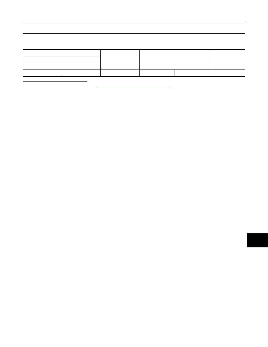
Check voltage between IPDM E/R harness connector and ground.
Is the inspection result normal?
YES
>> Replace BCM. Refer to
BCS-98, "Removal and Installation"
NO
>> Replace IPDM E/R.
(+)
(–)
Condition
Voltage (V)
(Approx.)
IPDM E/R
Connector
Terminal
E10
27
Ground
Ignition switch
OFF or ACC
6 - 16