Nissan Quest E52. Manual - part 941
PCS
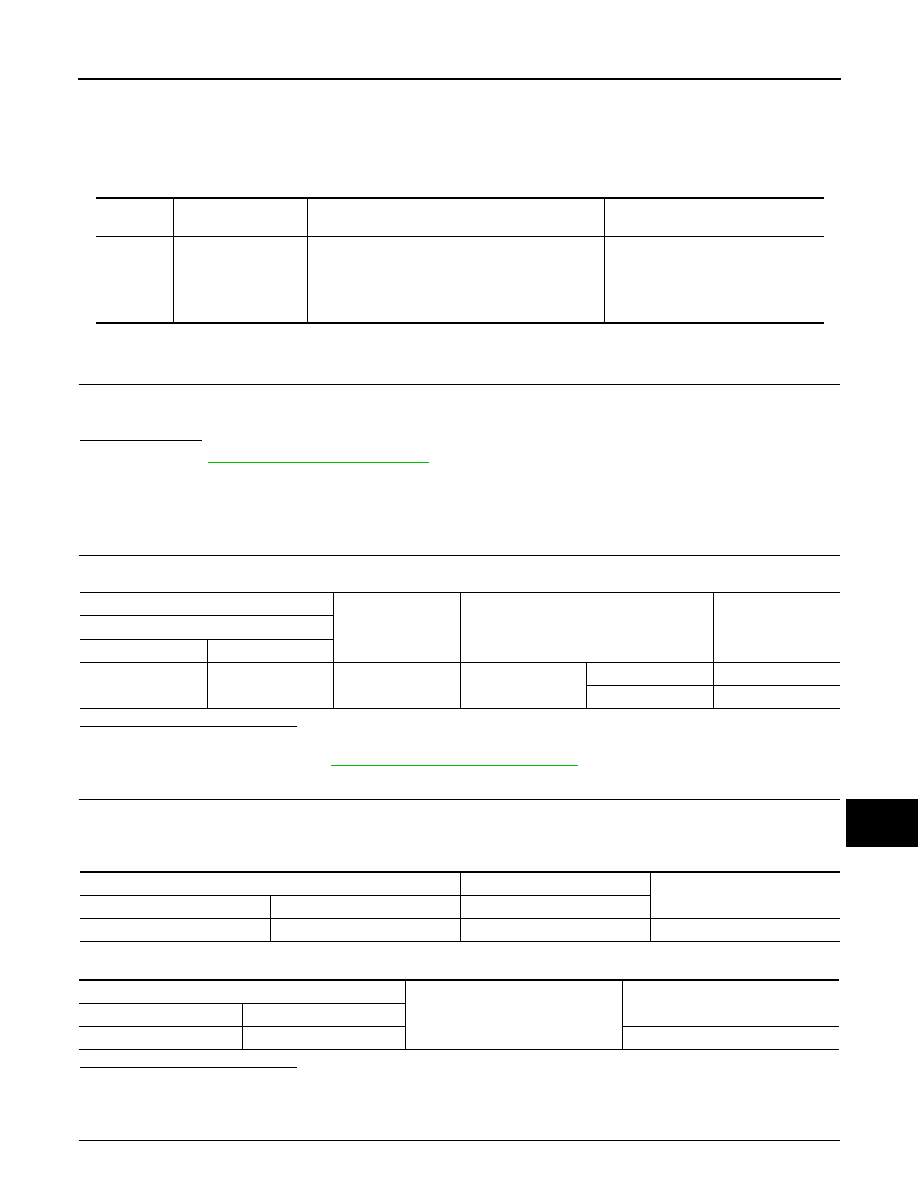
B2616 IGNITION RELAY CIRCUIT
PCS-61
< DTC/CIRCUIT DIAGNOSIS >
[POWER DISTRIBUTION SYSTEM]
C
D
E
F
G
H
I
J
K
L
B
A
O
P
N
B2616 IGNITION RELAY CIRCUIT
DTC Logic
INFOID:0000000009652885
DTC DETECTION LOGIC
DTC CONFIRMATION PROCEDURE
1.
PERFORM DTC CONFIRMATION PROCEDURE
1.
Turn ignition switch ON, and wait for 1 second or more.
2.
Check “Self-diagnosis result” with CONSULT.
Is DTC detected?
YES
>> Go to
NO
>> INSPECTION END
Diagnosis Procedure
INFOID:0000000009652886
1.
CHECK IGNITION RELAY (FUSE BLOCK) CONTROL SIGNAL
Check voltage between BCM harness connector and ground.
Is the inspection result normal?
YES
>> GO TO 2.
NO
>> Replace BCM. Refer to
BCS-98, "Removal and Installation"
2.
CHECK IGNITION RELAY (FUSE BLOCK) CONTROL SIGNAL CIRCUIT
1.
Turn ignition switch OFF.
2.
Disconnect BCM connector and ignition relay (fuse block).
3.
Check continuity between BCM harness connector and ignition relay (fuse block) harness connector.
4.
Check continuity between BCM harness connector and ground.
Is the inspection result normal?
YES
>> GO TO 3.
NO
>> Repair or replace harness.
3.
CHECK IGNITION RELAY (FUSE BLOCK)
DTC No.
Trouble diagnosis
name
DTC detecting condition
Possible cause
B2616
BCM
The following status are compared, and it does not
agree for 1 second or more.
• State of ignition relay (fuse block) control judg-
ment in BCM
• State of ignition relay (fuse block) control signal
• Harness or connectors [Ignition re-
lay (fuse block) control signal cir-
cuit]
• BCM
• Ignition relay (fuse block)
(+)
(–)
Condition
Voltage (V)
(Approx.)
BCM
Connector
Terminal
M124
99
Ground
Ignition switch
OFF or ACC
0 - 0.5
ON
9 - 16
BCM
Ignition relay (fuse block)
Continuity
Connector
Terminal
Terminal
M124
99
Coil upstream side
Existed
BCM
Ground
Continuity
Connector
Terminal
M124
99
Not existed