Nissan Quest E52. Manual - part 944
PCS
PUSH-BUTTON IGNITION SWITCH
PCS-73
< DTC/CIRCUIT DIAGNOSIS >
[POWER DISTRIBUTION SYSTEM]
C
D
E
F
G
H
I
J
K
L
B
A
O
P
N
Is the inspection result normal?
YES
>> INSPECTION END
NO
>> Replace push-button ignition switch.
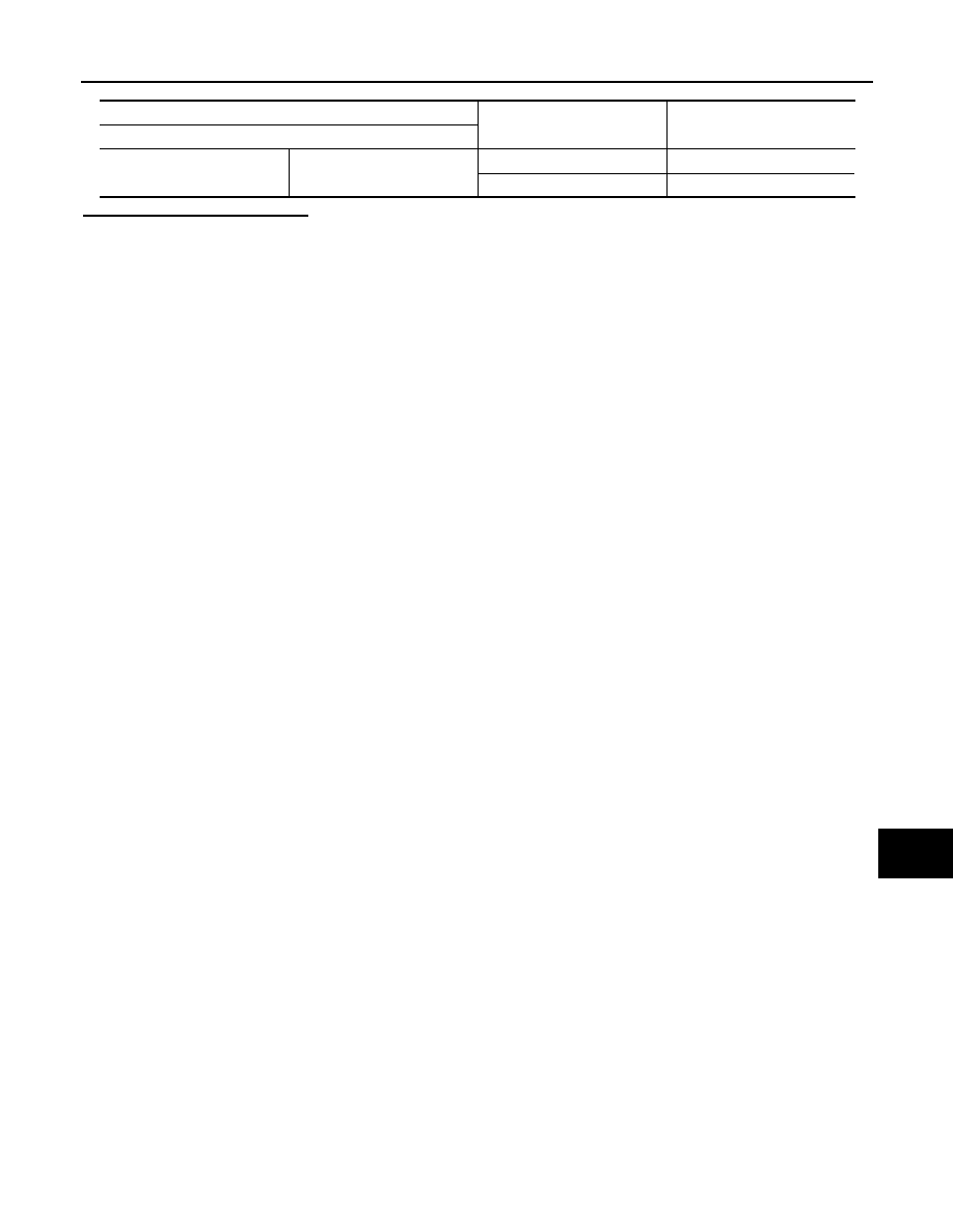
Push-button ignition switch
Condition
Continuity
Terminal
4
1
Pressed
Existed
Not pressed
Not existed