Nissan Quest E52. Manual - part 903


  Index      Nissan     Nissan Quest E52 (2011-2014 year) - Service and Repair Manual


Search            


Content   ..  901  902  903  904   ..


Nissan Quest E52. Manual - part 903


MWI

METER SYSTEM

MWI-17

< SYSTEM DESCRIPTION >

C

D

E

F

G

H

I

J

K

L

M

B

A

O

P

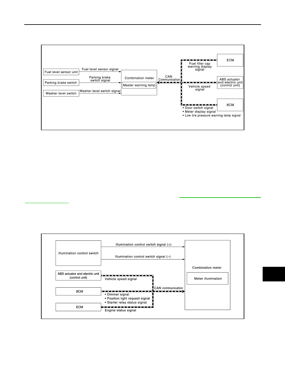
MASTER WARNING LAMP : System Description

INFOID:0000000009651477

SYSTEM DIAGRAM

DESCRIPTION

When receiving a signal from each unit, switch, or sensor, the combination meter turns ON/OFF the master
warning lamp in synchronization with the following warnings on the information display.
• Door open warning
• Parking brake release warning
• Low fuel warning
• Low washer fluid warning
• NO KEY warning
• Low tire pressure warning
• Fuel filler cap warning
NOTE:
For details on warnings displayed on the information display, refer to 

MWI-21, "INFORMATION DISPLAY :

System Description"

.

METER ILLUMINATION CONTROL

METER ILLUMINATION CONTROL : System Description

INFOID:0000000009651478

SYSTEM DIAGRAM

DESCRIPTION

Meter Illumination On/off Control Function

• Combination meter turns ON meter illumination when the following condition is satisfied:
- Ignition switch ON
• Combination meter turns OFF meter illumination when any of the following condition is satisfied:

JSNIA4137GB

JSNIA4138GB

MWI-18

< SYSTEM DESCRIPTION >

METER SYSTEM

- During a crank with vehicle speed less than 1 km/h (0.6 MPH)
- Ignition switch OFF or ACC
• The combination meter receives the following signals to control meter illumination.

Meter Illumination Control Function

• Combination meter controls meter illumination, based on the following signal.
- Dimmer signal (for U.S.A)
- Position light request signal (for Canada)
• The combination meter switches mode between Daytime mode and Nighttime mode, according to the fol-

lowing conditions.

*: For further information, refer to 

INL-17, "AUTO LIGHT ADJUSTMENT SYSTEM : System Description"

.

• The operation of the illumination control switch allows the brightness adjustment of meter illumination.

Signal Path

METER EFFECT FUNCTION

Signal name

Signal path

Ignition signal

Engine status signal

ECM 

 Combination meter

Vehicle speed signal

ABS actuator and control unit (control unit) 

 Combination meter

Starter relay status signal

BCM 

 Combination meter

Condition

Meter illumination

For U.S.A

For Canada

Combination switch
(lighting switch)

1ST or 2ND position

Outdoor: Bright*

Daytime mode

Nighttime mode

Outdoor: Dark*

Nighttime mode

Nighttime mode

AUTO POSITION

Outdoor: Bright*

Daytime mode

Daytime mode

Outdoor: Dark*

Nighttime mode

Nighttime mode

Off

Daytime mode

Daytime mode

Meter illumination

The number of adjustable 

steps

Daytime

22 step

Nighttime

22 step

Signal name

Signal source

Ignition signal

Dimmer signal (for U.S.A)

BCM  

Combination 

meter

Position light request signal (for Canada)

BCM  

Combination 

meter

MWI

METER SYSTEM

MWI-19

< SYSTEM DESCRIPTION >

C

D

E

F

G

H

I

J

K

L

M

B

A

O

P

METER EFFECT FUNCTION : System Description

INFOID:0000000009651479

SYSTEM DIAGRAM

DESCRIPTION

Engine-start Effect Function

When recognizing an engine start, the combination meter controls the following items for producing the effect.
• Speedometer
• Tachometer
• Engine coolant temperature gauge
• Fuel gauge
• Meter illumination

Meter and Illumination Operations During Engine-start Effect

The combination meter controls the following items during the engine-start effect.

NOTE:
The pointers are stopped and illumination is turned off while cranking the engine.

Engine Start Judgement

The combination meter judges “engine-start” and activates the engine-start effect only once when the follow-
ing operational conditions are all satisfied.

JSNIA4139GB

Control item

Operation

Speedometer

Sweeps the pointer.

Tachometer

Sweeps the pointer.

Engine coolant temperature gauge

Stops the pointer.

Fuel gauge

Stops the pointer.

Pointer

Turns on the illumination at the normal brightness level.

Printed area of the dial

Turns on the illumination at the effect level.

Illumination ring

Increases the brightness to the effect level in stages.

Information display (Dot matrix display and segment 
display)

Turns on the illumination at the normal brightness level.

Operational condition

Ignition switch

ON position

Vehicle speed

Less than 1 km/h (0.6 MPH)

Engine state

Other than the time of cranking the engine

500 rpm or more

MWI-20

< SYSTEM DESCRIPTION >

METER SYSTEM

NOTE:
ENGINE-START EFFECT exits when any of the above operational conditions is cancelled during the engine-
start effect.

Signal Path

The combination meter judges “engine-start”, according to the following signals and activates the engine-start
effect function.

NOTE:

The engine-start effect function ends if any one of the above conditions is lost during the activation of this function.

Driver Welcome Function

BCM transmits a meter ring illumination request signal to the illumination meter when all the following opera-
tional conditions are satisfied. When receiving the meter ring illumination request signal from BCM via CAM
communication, the combination meter increases illumination brightness of the combination meter to the set
brightness level in stages. After a certain period of time, the meter illumination gradually dims to be turned
OFF.

*: Close the driver side door with the intelligent key left inside the vehicle.

Signal Path

The combination meter receives the following signals to control meter ring illumination.

Shift position

“P”

Information display (SET-
TING)

The setting of “EFFECT” is “ON”

Operational condition

Signal name

Signal source

Ignition signal

Starter relay status signal

BCM 

 Combination meter

Engine speed signal

ECM 

 Combination meter

Engine status signal

Vehicle speed signal

ABS actuator and electric unit (control unit) 

 Combination meter

Shift position signal

TCM  

Combination 

meter

Operational condition

Ignition switch

LOCK position

Driver side door

Open 

 Close

*

Signal name

Signal source

Ignition signal

Door switch signal 
(driver)

BCM 

 Combination meter

Door lock/unlock sta-
tus signal

BCM 

 Combination meter


Content   ..  901  902  903  904   ..