Nissan Quest E52. Manual - part 821
REAR CONSOLE ASSEMBLY
IP-33
< REMOVAL AND INSTALLATION >
C
D
E
F
G
H
I
K
L
M
A
B
IP
N
O
P
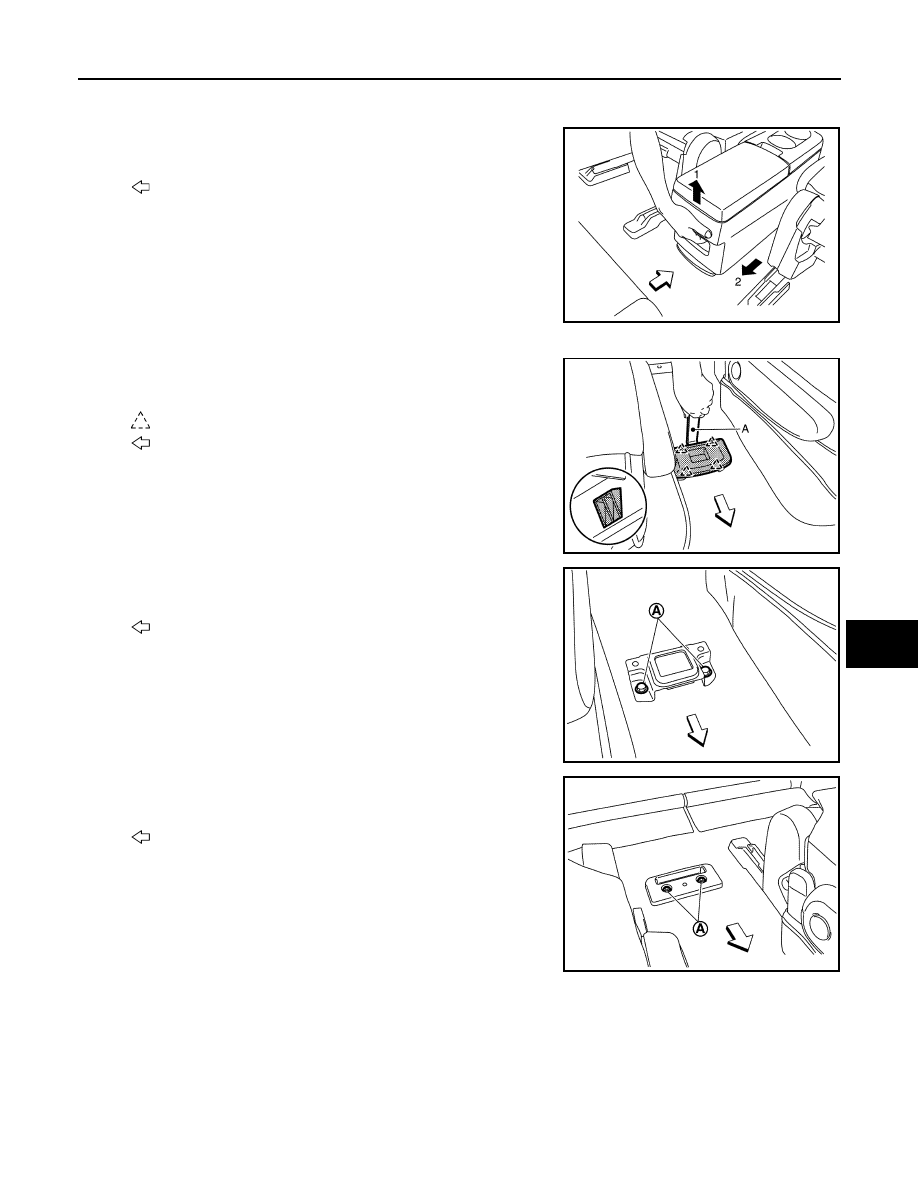
REMOVAL
1.
Remove rear console assembly.
Pull up latch handle of console latch assembly, and then remove
rear console assembly sliding toward vehicle rear.
2.
Remove rear console bases and brackets.
a.
Insert a remover tool (A) between rear console front base and
body floor to disengage the pawls as shown in the figure.
b.
Remove fixing bolts (A), and then remove rear console front
bracket.
c.
Remove fixing bolts (A), and then remove rear console rear
base.
d.
Remove fixing bolts, and then remove rear console rear bracket.
INSTALLATION
Install in the reverse order of removal.
Disassembly and Assembly
INFOID:0000000009650906
Disassembly and Assembly of Rear Console Assembly.
CAUTION:
: Vehicle front
JMJIA6166ZZ
Pawl
: Vehicle front
JMJIA6167ZZ
: Vehicle front
JMJIA6168ZZ
: Vehicle front
JMJIA6169ZZ