Nissan Quest E52. Manual - part 819


  Index      Nissan     Nissan Quest E52 (2011-2014 year) - Service and Repair Manual


Search            


Content   ..  817  818  819  820   ..


Nissan Quest E52. Manual - part 819


INSTRUMENT PANEL ASSEMBLY

IP-25

< REMOVAL AND INSTALLATION >

C

D

E

F

G

H

I

K

L

M

A

B

IP

N

O

P

d.

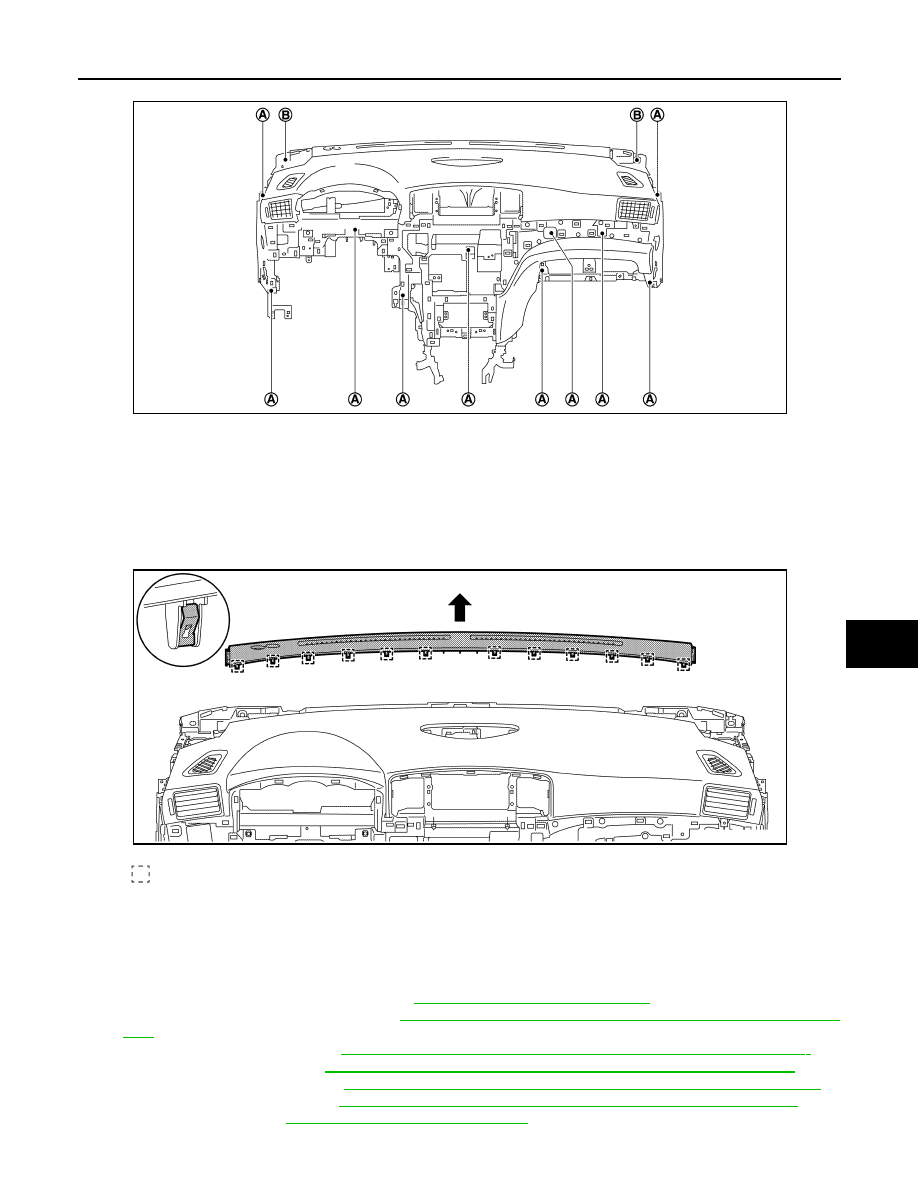
Remove instrument panel assembly fixing screws (A), bolts (B).

e.

Remove instrument panel assembly from passenger door opening portion.

CAUTION:

• Cover tool with a shop cloth to prevent windshield glass from being damaged.
• Cover center console upper surface with a shop cloth to prevent it from being damaged.
• When removing instrument panel assembly, 2 workers are required so as to prevent it from drop-

ping.

45. Remove instrument upper garnish.

a.

Insert a remover tool between instrument upper garnish and instrument panel assembly to disengage
metal clips.

b.

Remove instrument upper garnish.

46. Remove the following parts after removing instrument panel assembly.

• Front passenger air bag module: Refer to 

SR-18, "Removal and Installation"

.

• Side ventilator grille (LH/RH): Refer to 

VTL-10, "SIDE VENTILATOR GRILLE : Removal and Installa-

tion"

.

• Center ventilator duct: Refer to 

VTL-10, "CENTER VENTILATOR DUCT : Removal and Installation"

.

• Side ventilator duct: Refer to 

VTL-10, "CENTER VENTILATOR DUCT : Removal and Installation"

.

• Front defroster nozzle: Refer to 

VTL-11, "FRONT DEFROSTER NOZZLE : Removal and Installation"

.

• Side defroster nozzle: Refer to 

VTL-11, "SIDE DEFROSTER NOZZLE : Removal and Installation"

.

• GPS antenna: Refer to 

AV-629, "Removal and Installation"

.

JMJIA6160ZZ

: Metal clip

JMJIA6161ZZ

IP-26

< REMOVAL AND INSTALLATION >

INSTRUMENT PANEL ASSEMBLY

• Inside key antenna (instrument center) and harness clamp. Refer to 

DLK-488, "INSTRUMENT CENTER

: Removal and Installation"

.

INSTALLATION

Note the following items, and then install in the reverse order of removal.

CAUTION:

• Never use the steering wheel mounting nut after removal, replace with the new nut.
• Never use the driver air bag module mounting bolts after removal, replace with the new bolts.
• Never use the passenger air bag module mounting bolt after removal, replace with the new bolt.

CENTER CONSOLE ASSEMBLY

IP-27

< REMOVAL AND INSTALLATION >

C

D

E

F

G

H

I

K

L

M

A

B

IP

N

O

P

CENTER CONSOLE ASSEMBLY

Exploded View

INFOID:0000000009650901

CENTER CONSOLE ASSEMBLY (With NAVI)

JMJIA6162ZZ

1.

Center console upper finisher

2.

Center console body assembly

3.

Console sub-harness

4.

Console pocket assembly

5.

Console pocket rail

6.

Center console center bracket 2

7.

VTR jacks

8.

Console tray

9.

Power outlet

10. USB connector

11.

Mat

12. Center console assembly

13. Cap

14. Center console front bracket

15. Center console rear bracket

16. Center console center bracket 1

: Metal clip

 : Indicates that the part is connected at points with same symbol in actual vehicle.

IP-28

< REMOVAL AND INSTALLATION >

CENTER CONSOLE ASSEMBLY

CENTER CONSOLE ASSEMBLY (Without NAVI)

Removal and Installation

INFOID:0000000009650902

Removal and Installation

CAUTION:

When removing, always use a remover tool that is made of plastic.

1.

Remove driver seat assembly and passenger seat assembly.
• Manual seat: Refer to 

SE-88, "Removal and Installation"

.

• Power seat: Refer to 

SE-102, "Removal and Installation"

.

JMJIA6163ZZ

1.

Center console upper finisher

2.

Center console body assembly

3.

Console pocket assembly

4.

Console pocket rail

5.

Center console center bracket 2

6.

Console tray

7.

Mat

8.

Center console assembly

9.

Cap

10. Center console front bracket

11.

Center console rear bracket

12. Center console center bracket 1

: Metal clip

 : Indicates that the part is connected at points with same symbol in actual vehicle.


Content   ..  817  818  819  820   ..