Nissan Quest E52. Manual - part 668
BACK DOOR FINISHER
EXT-47
< REMOVAL AND INSTALLATION >
C
D
E
F
G
H
I
J
L
M
A
B
EXT
N
O
P
BACK DOOR FINISHER
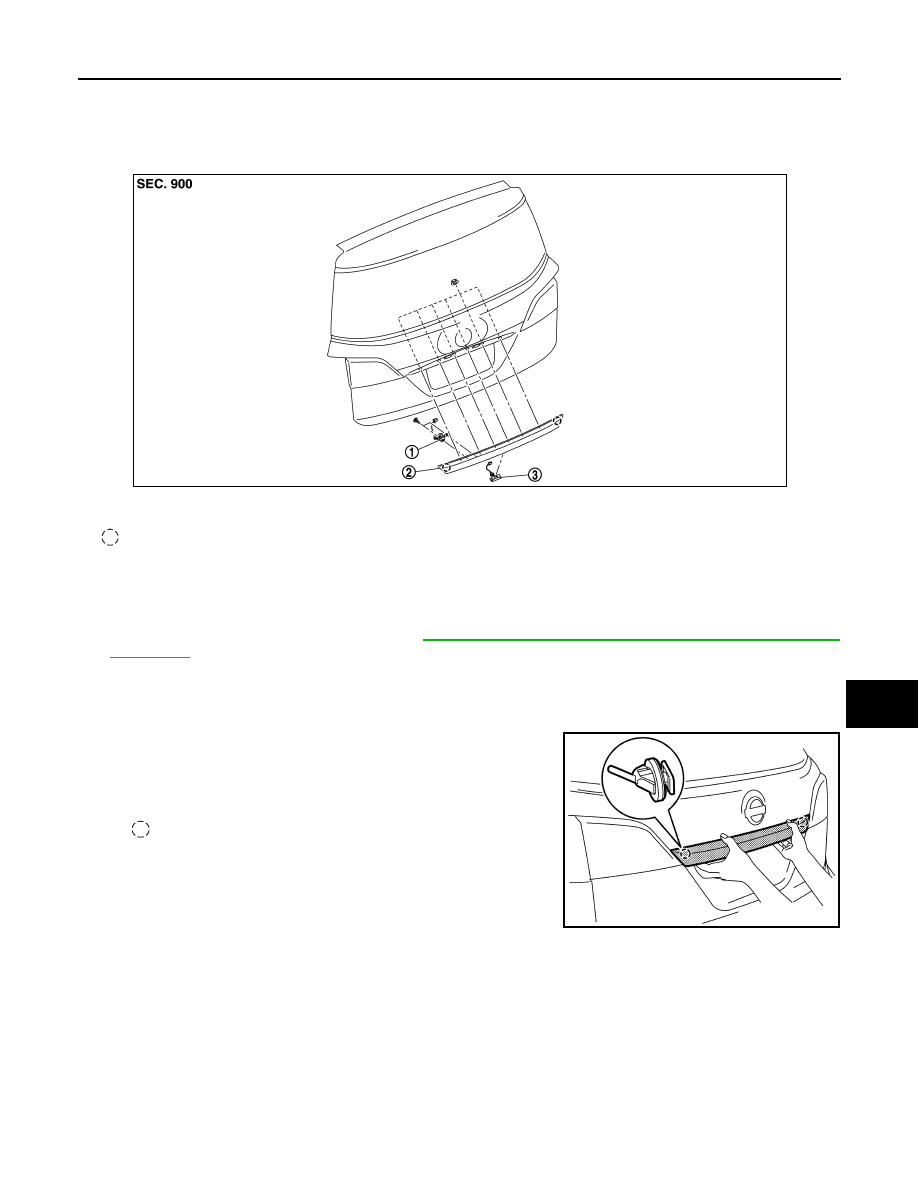
Exploded View
INFOID:0000000009650523
Removal and Installation
INFOID:0000000009650524
REMOVAL
1.
Remove back door lower finisher. Refer to
INT-48, "BACK DOOR LOWER FINISHER : Removal and
.
2.
Remove back door finisher mounting nuts.
3.
Disconnect back door opener request switch and rear view camera harness connectors.
4.
Remove harness grommet.
5.
Pull back door finisher diagonally downward, disengage fixing
clips of back door finisher, and then remove back door finisher.
CAUTION:
Never pull back door finisher strongly.
INSTALLATION
Install in the reverse order of removal.
1.
Rear view camera
2.
Back door finisher
3.
Back door opener request switch
: Clip
JMKIA8278ZZ
: Clip
JMKIA8279ZZ