Nissan Quest E52. Manual - part 653
EXL-216
< REMOVAL AND INSTALLATION >
[HALOGEN TYPE]
FRONT FOG LAMP
FRONT FOG LAMP
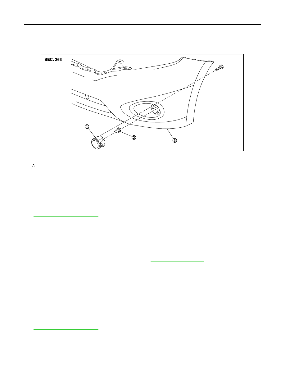
Exploded View
INFOID:0000000009653195
Removal and Installation
INFOID:0000000009653196
CAUTION:
Disconnect the battery negative terminal or the fuse.
REMOVAL
1.
Remove front fender protector (front) fixing screws and clips, and then keep a service area. Refer to
23, "Removal and Installation"
.
2.
Disconnect front fog lamp connector.
3.
Remove front fog lamp mounting bolt.
4.
Disengage fixing pawl, and then remove front fog lamp.
INSTALLATION
Note the following item, and then install in the reverse order of removal.
CAUTION:
After installation, perform aiming adjustment. Refer to
Replacement
INFOID:0000000009653197
CAUTION:
• Disconnect the battery negative terminal or the fuse.
• Never touch the glass of bulb directly by hand. Keep grease and other oily matters away from it.
• Never touch bulb by hand while it is lit or right after being turned off.
• Never leave bulb out of lamp reflector for a long time because dust, moisture smoke, etc. may affect
the performance of lamp. When replacing bulb, be sure to replace it with new one.
FRONT FOG LAMP BULB
1.
Remove front fender protector (front) fixing screws and clips, and then keep a service area. Refer to
23, "Removal and Installation"
.
1.
Front fog lamp
2.
Halogen bulb
3.
Front bumper fascia
: Pawl
JMLIA1457ZZ