Nissan Quest E52. Manual - part 651
EXL-208
< SYMPTOM DIAGNOSIS >
[HALOGEN TYPE]
BOTH SIDE FRONT FOG LAMPS ARE NOT TURNED ON
BOTH SIDE FRONT FOG LAMPS ARE NOT TURNED ON
Description
INFOID:0000000009653185
The front fog lamps are not turned ON in any condition.
Diagnosis Procedure
INFOID:0000000009653186
1.
CHECK FRONT FOG LAMP FUSE
1.
Turn ignition switch OFF.
2.
Check that the following fuse is not fusing.
Is the inspection result normal?
YES
>> GO TO 3.
NO
>> GO TO 2.
2.
CHECK FRONT FOG LAMP SHORT CIRCUIT
1.
Disconnect front fog connector and IPDM E/R connector.
2.
Check continuity between IPDM E/R harness connector and ground.
Is the inspection result normal?
YES
>> Replace fuse. (Replace IPDM E/R if the fuse is fusing again.)
NO
>> Repair or replace harness. And then replace the fuse.
3.
COMBINATION SWITCH INSPECTION
Check combination switch. Refer to
Is the inspection result normal?
YES
>> GO TO 4.
NO
>> Repair or replace the malfunctioning part.
4.
CHECK FRONT FOG LAMP REQUEST SIGNAL INPUT
CONSULT DATA MONITOR
1.
Select “FR FOG REQ” of IPDM E/R data monitor item.
2.
With operating the front fog lamp switch, check the monitor status.
Is the item status normal?
YES
>> GO TO 5.
NO
>> Replace BCM. Refer to
BCS-98, "Removal and Installation"
5.
FRONT FOG LAMP CIRCUIT INSPECTION
Check the front fog lamp circuit. Refer to
EXL-191, "Component Function Check"
.
Is the inspection result normal?
YES
>> Refer to
GI-42, "Intermittent Incident"
.
NO
>> Repair or replace the malfunctioning part.
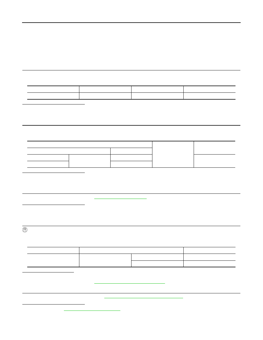
Unit
Location
Fuse No.
Capacity
Front fog lamp
IPDM E/R
#58
15 A
IPDM E/R
Ground
Continuity
Connector
Terminal
RH
E345
86
Not existed
LH
87
Monitor item
Condition
Monitor status
FR FOG REQ
Front fog lamp switch
(With lighting switch 2ND)
ON
On
OFF
Off