Nissan Quest E52. Manual - part 629
EXL-120
< SERVICE DATA AND SPECIFICATIONS (SDS)
[XENON TYPE]
SERVICE DATA AND SPECIFICATIONS (SDS)
SERVICE DATA AND SPECIFICATIONS (SDS)
SERVICE DATA AND SPECIFICATIONS (SDS)
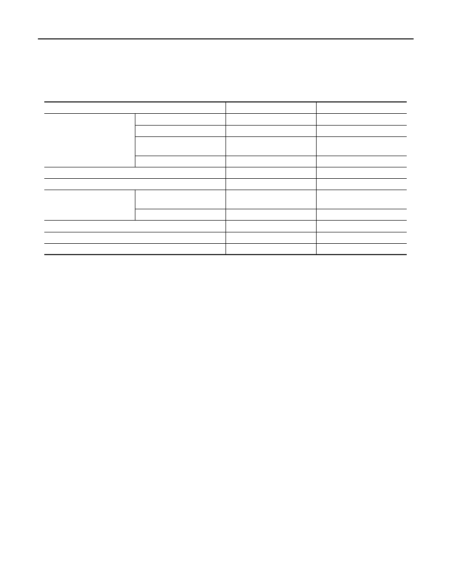
Bulb Specifications
INFOID:0000000009653115
Item
Type
Wattage (W)
Front combination lamp
Headlamp (HI)
HB3 (Halogen)
60
Headlamp (LO)
D2S (Xenon)
35
Front turn signal lamp/
Parking lamp
S25 (Amber)
27/8
Front side marker lamp
W5W
5
Front fog lamp
H8
35
Side turn signal lamp (integrated into the door mirror)
LED
—
Rear combination lamp
Stop lamp/
Tail lamp (side marker)
W21/5W
21/5
Rear turn signal lamp
WY21W (Amber)
21
Back-up lamp
W16W
16
License plate lamp
W5W
5
High-mounted stop lamp
LED
—