Nissan Quest E52. Manual - part 460


  Index      Nissan     Nissan Quest E52 (2011-2014 year) - Service and Repair Manual


Search            


Content   ..  458  459  460  461   ..


Nissan Quest E52. Manual - part 460


EC-50

< SYSTEM DESCRIPTION >

[VQ35DE]

SYSTEM

The evaporative emission system is used to reduce hydrocarbons emitted into the atmosphere from the fuel
system. This reduction of hydrocarbons is accomplished by activated charcoals in the EVAP canister.
The fuel vapor in the sealed fuel tank is led into the EVAP canister which contains activated carbon and the
vapor is stored there when the engine is not operating or when refueling to the fuel tank.
The vapor in the EVAP canister is purged by the air through the purge line to the intake manifold when the
engine is operating. EVAP canister purge volume control solenoid valve is controlled by ECM. When the
engine operates, the flow rate of vapor controlled by EVAP canister purge volume control solenoid valve is
proportionally regulated as the air flow increases.
EVAP canister purge volume control solenoid valve also shuts off the vapor purge line during decelerating and
idling.

INTAKE VALVE TIMING CONTROL

INTAKE VALVE TIMING CONTROL : System Description

INFOID:0000000009650964
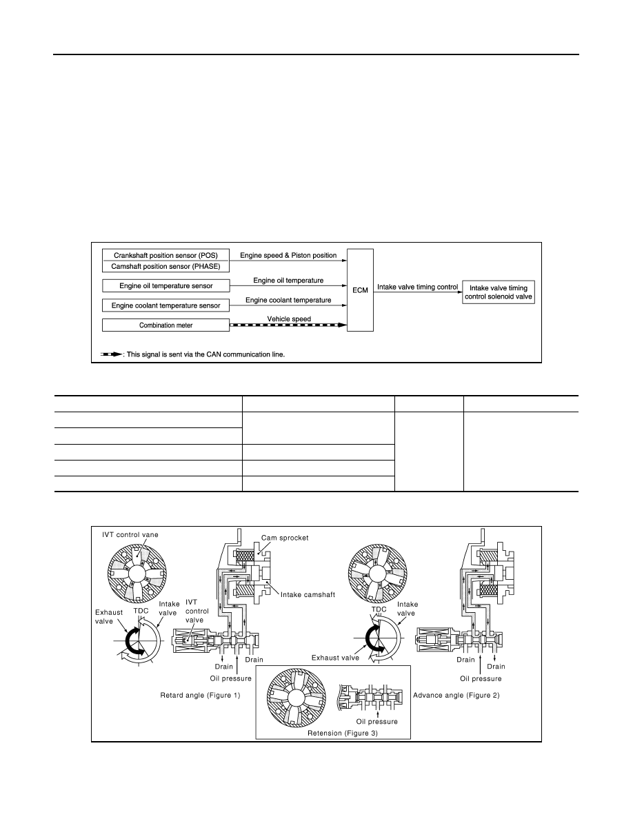
SYSTEM DIAGRAM

INPUT/OUTPUT SIGNAL CHART

*: This signal is sent to the ECM via the CAN communication line

SYSTEM DESCRIPTION

This mechanism hydraulically controls cam phases continuously with the fixed operating angle of the intake
valve.
The ECM receives signals such as crankshaft position, camshaft position, engine speed, and engine coolant
temperature. Then, the ECM sends ON/OFF pulse duty signals to the intake valve timing (IVT) control sole-

JMBIA1830GB

Sensor

Input signal to ECM

ECM function

Actuator

Crankshaft position sensor (POS)

Engine speed and piston position

Intake valve 
timing control

Intake valve timing control 
solenoid valve

Camshaft position sensor (PHASE)

Engine oil temperature sensor

Engine oil temperature

Engine coolant temperature sensor

Engine coolant temperature

Combination meter

Vehicle speed*

JMBIA0060GB

SYSTEM

EC-51

< SYSTEM DESCRIPTION >

[VQ35DE]

C

D

E

F

G

H

I

J

K

L

M

A

EC

N

P

O

noid valve depending on driving status. This makes it possible to control the shut/open timing of the intake
valve to increase engine torque in low/mid speed range and output in high-speed range.

FUEL FILLER CAP WARNING SYSTEM

FUEL FILLER CAP WARNING SYSTEM : System Description

INFOID:0000000009650965

SYSTEM DIAGRAM

INPUT/OUTPUT SIGNAL CHART

Input

*: This signal is sent to the ECM via the CAN communication line.

Output

*: This signal is sent to the combination meter via the CAN communication line.

SYSTEM DESCRIPTION

The fuel filler cap warning system alerts the driver to the prevention of the fuel filler being left uncapped and
malfunction occurrences after refueling, by turning ON the fuel filler cap warning display on the combination
meter.
ECM judges a refueled state, based on a fuel level signal transmitted from the combination meter.
When a very small leak is detected through the EVAP leak diagnosis performed after judging the refueled
state, ECM transmits a fuel filler cap warning display signal (request for display ON) to the combination meter
via CAN communication. 
When receiving the signal, the combination meter turns ON the fuel filler cap warning display.

CAUTION:

Check fuel filler cap installation condition when the fuel filler cap warning display turns ON.

Reset Operation

The fuel filler cap warning lamp tunes OFF, according to any condition listed below:
• Reset operation is performed by operating the meter control switch on the combination meter.
- When the reset operation is performed, the combination meter transmits a fuel filler cap warning reset signal

to ECM via CAN communication. ECM transmits a fuel filler cap warning display signal (request for display
OFF) to the combination meter via CAN communication. When receiving the signal, the combination meter
turns OFF the fuel filler cap warning display.

• EVAP leak diagnosis result is normal.

Unit/Sensor

Input signal to ECM

ECM function

EVAP control system pressure sensor

Pressure in purge line

Fuel filler cap warning control

Combination meter

Fuel level sensor signal

*

Fuel filler cap warning reset signal

*

JSBIA1456GB

Unit

Output signal

Actuator

ECM

Fuel filler cap warning display signal

*

Combination meter

EC-52

< SYSTEM DESCRIPTION >

[VQ35DE]

SYSTEM

• Fuel refilled.
• DTC erased by using CONSULT.
NOTE:
MIL turns ON if a malfunction is detected in leak diagnosis results again at the trip after the fuel filler cap warn-
ing display turns ON/OFF.

VARIABLE INDUCTION AIR SYSTEM

VARIABLE INDUCTION AIR SYSTEM : System Description

INFOID:0000000009650966

SYSTEM DIAGRAM

INPUT/OUTPUT SIGNAL CHART

*: ECM determines the start signal status by the signals of engine speed and battery voltage.

JMBIA1831GB

Sensor

Input signal to ECM

ECM function

Actuator

Crankshaft position sensor (POS)
Camshaft position sensor (PHASE)

Engine speed*

VIAS control

VIAS control solenoid valve 1
VIAS control solenoid valve 2

Mass air flow sensor

Amount of intake air

Engine coolant temperature sensor

Engine coolant temperature

Throttle position sensor

Throttle position

Accelerator pedal position sensor

Accelerator pedal position

Battery

Battery voltage*

SYSTEM

EC-53

< SYSTEM DESCRIPTION >

[VQ35DE]

C

D

E

F

G

H

I

J

K

L

M

A

EC

N

P

O

SYSTEM DESCRIPTION

In the medium speed range, the ECM sends the ON signal to the VIAS control solenoid valve. This signal
introduces the intake manifold vacuum into the power valve actuator and therefore closes the power valve.
Under this condition, the pressure waves of the exhaust stroke do not disturb the pressure waves of the intake
stroke of each opposite bank. Therefore, charging efficiency is increased together with the effect of the long
intake passage.
However, in the high speed range, the ECM sends the OFF signal to the VIAS control solenoid valve and the
power valve is opened. Under this condition, the pressure waves of intake stroke are resonant with those of
each opposite bank exhaust stroke. Therefore, charging efficiency is also increased.
In addition, both valves 1 and 2 are opened or closed in other ranges mentioned above. Thus maximum
charging efficiency is obtained for the various driving conditions.

VACUUM HOSE DRAWING

JMBIA0181GB


Content   ..  458  459  460  461   ..