Nissan Quest E52. Manual - part 458


  Index      Nissan     Nissan Quest E52 (2011-2014 year) - Service and Repair Manual


Search            


Content   ..  456  457  458  459   ..


Nissan Quest E52. Manual - part 458


EC-42

< SYSTEM DESCRIPTION >

[VQ35DE]

SYSTEM

FUEL SHUT-OFF

Fuel to each cylinder is cut off during deceleration, operation of the engine at excessively high speeds or oper-
ation of the vehicle at excessively high speeds.

ELECTRIC IGNITION SYSTEM

ELECTRIC IGNITION SYSTEM : System Description

INFOID:0000000009650958
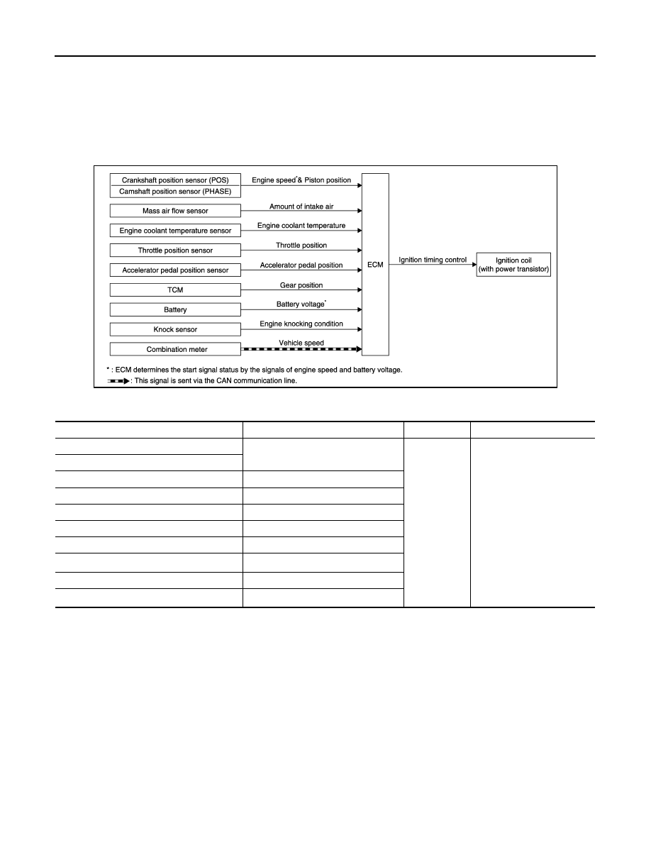
SYSTEM DIAGRAM

INPUT/OUTPUT SIGNAL CHART

*1: This signal is sent to the ECM via the CAN communication line.

*2: ECM determines the start signal status by the signals of engine speed and battery voltage.

SYSTEM DESCRIPTION

Ignition order: 1 - 2 - 3 - 4 - 5 - 6
The ignition timing is controlled by the ECM to maintain the best air-fuel ratio for every running condition of the
engine. The ignition timing data is stored in the ECM.
The ECM receives information such as the injection pulse width and camshaft position sensor (PHASE) sig-
nal. Computing this information, ignition signals are transmitted to the power transistor.
During the following conditions, the ignition timing is revised by the ECM according to the other data stored in
the ECM.
• At starting
• During warm-up
• At idle
• At low battery voltage
• During acceleration

JMBIA1834GB

Sensor

Input signal to ECM

ECM function

Actuator

Crankshaft position sensor (POS)

Engine speed*

2

Piston position

Ignition timing 
control

Ignition coil
(with power transistor)

Camshaft position sensor (PHASE)

Mass air flow sensor

Amount of intake air

Engine coolant temperature sensor

Engine coolant temperature

Throttle position sensor

Throttle position

Accelerator pedal position sensor

Accelerator pedal position

TCM

Gear position

Battery

Battery voltage*

2

Knock sensor

Engine knocking

Combination meter

Vehicle speed*

1

SYSTEM

EC-43

< SYSTEM DESCRIPTION >

[VQ35DE]

C

D

E

F

G

H

I

J

K

L

M

A

EC

N

P

O

The knock sensor retard system is designed only for emergencies. The basic ignition timing is programmed
within the anti-knocking zone, if recommended fuel is used under dry conditions. The retard system does not
operate under normal driving conditions. If engine knocking occurs, the knock sensor monitors the condition.
The signal is transmitted to the ECM. The ECM retards the ignition timing to eliminate the knocking condition.

AIR CONDITIONING CUT CONTROL

AIR CONDITIONING CUT CONTROL : System Description

INFOID:0000000009650959

SYSTEM DIAGRAM

INPUT/OUTPUT SIGNAL CHART

*1: This signal is sent to the ECM via the CAN communication line.

*2: ECM determines the start signal status by the signals of engine speed and battery voltage.

SYSTEM DESCRIPTION

This system improves engine operation when the air conditioner is used.
Under the following conditions, the air conditioner is turned OFF.
• When the accelerator pedal is fully depressed.
• When cranking the engine.
• At high engine speeds.
• When the engine coolant temperature becomes excessively high.

JMBIA1835GB

Sensor

Input signal to ECM

ECM function

Actuator

Crankshaft position sensor (POS)
Camshaft position sensor (PHASE)

Engine speed*

2

Air conditioner 
cut control

IPDM E/R

Air conditioner relay

Compressor

Engine coolant temperature sensor

Engine coolant temperature

Accelerator pedal position sensor

Accelerator pedal position

Battery

Battery voltage*

2

Refrigerant pressure sensor

Refrigerant pressure

Power steering pressure sensor

Power steering operation

Combination meter

Vehicle speed*

1

BCM

Air conditioner ON signal*

1

EC-44

< SYSTEM DESCRIPTION >

[VQ35DE]

SYSTEM

• When operating power steering during low engine speed or low vehicle speed.
• When engine speed is excessively low.
• When refrigerant pressure is excessively low or high.

AUTOMATIC SPEED CONTROL DEVICE (ASCD)

AUTOMATIC SPEED CONTROL DEVICE (ASCD) : System Description

INFOID:0000000009650960

SYSTEM DIAGRAM

INPUT/OUTPUT SIGNAL CHART

*: This signal is sent to the ECM via the CAN communication line

BASIC ASCD SYSTEM

Refer to Owner's Manual for ASCD operating instructions.
Automatic Speed Control Device (ASCD) allows a driver to keep vehicle at predetermined constant speed
without depressing accelerator pedal. Driver can set vehicle speed in advance between approximately 40 km/
h (25 MPH) and 144 km/h (89 MPH).
ECM controls throttle angle of electric throttle control actuator to regulate engine speed.
Operation status of ASCD is indicated by CRUISE on combination meter. If any malfunction occurs in the
ASCD system, it automatically deactivates control.
NOTE:
Always drive vehicle in a safe manner according to traffic conditions and obey all traffic laws.

SET OPERATION

Press MAIN switch. (The CRUISE on combination meter illuminates.)
When vehicle speed reaches a desired speed between approximately 40 km/h (25 MPH) and 144 km/h (89
MPH), press SET/COAST switch.

ACCELERATE OPERATION

If the RESUME/ACCELERATE switch is pressed during cruise control driving, increase the vehicle speed until
the switch is released or vehicle speed reaches maximum speed controlled by the system.
And then ASCD will maintain the new set speed.

CANCEL OPERATION

When any of following conditions exist, cruise operation will be canceled.
• CANCEL switch is pressed

JMBIA1826GB

Sensor

Input signal to ECM

ECM function

Actuator

ASCD brake switch

Brake pedal operation

ASCD vehicle speed control

Electric throttle control 
actuator

Stop lamp switch

Brake pedal operation

ASCD steering switch

ASCD steering switch operation

TCM

Gear position

Powertrain revolution*

Combination meter

Vehicle speed*

SYSTEM

EC-45

< SYSTEM DESCRIPTION >

[VQ35DE]

C

D

E

F

G

H

I

J

K

L

M

A

EC

N

P

O

• More than 2 switches on ASCD steering switch are pressed at the same time (Set speed will be cleared)
• Brake pedal is depressed
• Selector lever position changed to N, P or R
• Vehicle speed decreased to 13 km/h (8 MPH) lower than the set speed
• TCS system is operated
• CVT control system has a malfunction. Refer to 

EC-381, "Description"

.

• Engine coolant temperature is slightly higher than the normal operating temperature
When the ECM detects any of the following conditions, the ECM will cancel the cruise operation and inform
the driver by blinking indicator lamp.
• Malfunction for some self-diagnoses regarding ASCD control: CRUISE will blink quickly.
If MAIN switch is turned to OFF while ASCD is activated, all of ASCD operations will be canceled and vehicle
speed memory will be erased.

COAST OPERATION

When the SET/COAST switch is pressed during cruise control driving, decrease vehicle set speed until the
switch is released. And then ASCD will maintain the new set speed.

RESUME OPERATION

When the RESUME/ACCELERATE switch is pressed after canceling operation other than pressing the MAIN
switch is performed, vehicle speed will return to last set speed. To resume vehicle set speed, vehicle condition
must meet following conditions.
• Brake pedal is released
• Selector lever position is other than P and N
• Vehicle speed is greater than 40 km/h (25 MPH) and less than 144 km/h (89 MPH)

COOLING FAN CONTROL

COOLING FAN CONTROL : System Description

INFOID:0000000009650961

SYSTEM DIAGRAM

INPUT/OUTPUT SIGNAL CHART

JMBIA1857GB

Sensor

Input signal to ECM

ECM function

Actuator

Crankshaft position sensor (POS)
Camshaft position sensor (PHASE)

Engine speed*

1

Piston position

Cooling fan 
control

IPDM E/R

Cooling fan relay

Cooling fan motor

Engine coolant temperature sensor

Engine coolant temperature

Refrigerant pressure sensor

Refrigerant pressure

Battery

Battery voltage*

1

Combination meter

Vehicle speed*

2

BCM

Air conditioner ON signal*

2


Content   ..  456  457  458  459   ..