Nissan Quest E52. Manual - part 459


  Index      Nissan     Nissan Quest E52 (2011-2014 year) - Service and Repair Manual


Search            


Content   ..  457  458  459  460   ..


Nissan Quest E52. Manual - part 459


EC-46

< SYSTEM DESCRIPTION >

[VQ35DE]

SYSTEM

*1: The ECM determines the start signal status by the signals of engine speed and battery voltage.

*2: This signal is sent to ECM via the CAN communication line.

SYSTEM DESCRIPTION

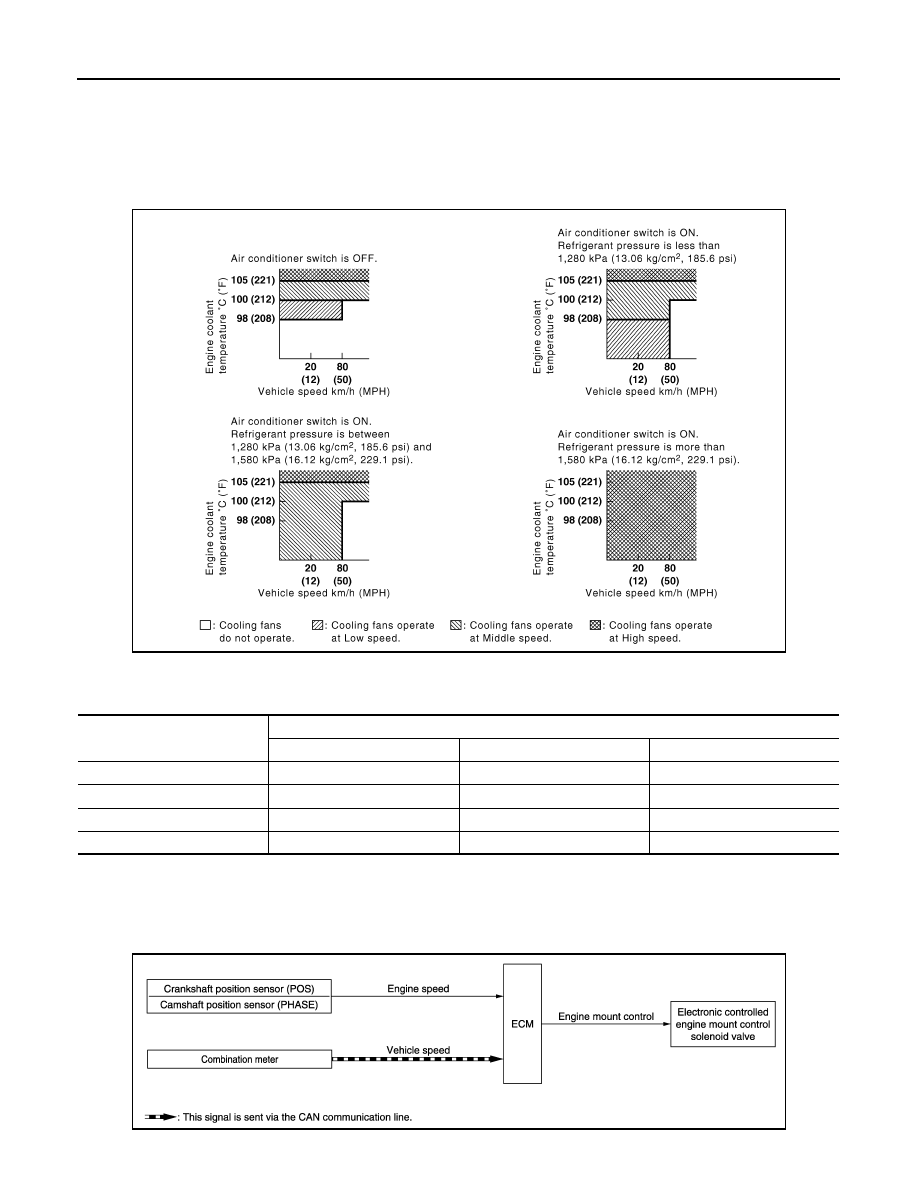
The ECM controls the cooling fan corresponding to the vehicle speed, engine coolant temperature, refrigerant
pressure, and air conditioner ON signal. The control system has 4-step control [HIGH/MIDDLE/LOW/OFF].

Cooling Fan Operation

Cooling Fan Relay Operation

The ECM controls cooling fan relays in the IPDM E/R through CAN communication line.

ELECTRONIC CONTROLLED ENGINE MOUNT

ELECTRONIC CONTROLLED ENGINE MOUNT : System Description

INFOID:0000000009650962

SYSTEM DIAGRAM

JMBIA0179GB

Cooling fan speed

Cooling fan relay

1

2

3

Stop (OFF)

OFF

OFF

OFF

Low (LOW)

ON

OFF

OFF

Middle (MID)

OFF

ON

OFF

High (HI)

OFF

ON

ON

JMBIA1827GB

SYSTEM

EC-47

< SYSTEM DESCRIPTION >

[VQ35DE]

C

D

E

F

G

H

I

J

K

L

M

A

EC

N

P

O

INPUT/OUTPUT SIGNAL CHART

*: This signal is sent to the ECM via the CAN communication line.

SYSTEM DESCRIPTION

The ECM controls the engine mount operation corresponding to the engine speed. The control system has a
2-step control [Soft/Hard]

ELECTRONIC CONTROLLED ENGINE MOUNT LINE DRAWING

Sensor

Input signal to ECM

ECM function

Actuator

Crankshaft position sensor (POS)
Camshaft position sensor (PHASE)

Engine speed

Engine mount 
control

Electronic controlled en-
gine mount control solenoid 
valve

Combination meter

Vehicle speed*

Vehicle condition

Engine mount control

Idle (With vehicle stopped)

Soft

Except above conditions

Hard

JMBIA2161ZZ

EC-48

< SYSTEM DESCRIPTION >

[VQ35DE]

SYSTEM

NOTE:
Do not use soapy water or any type of solvent while installing vacuum hose.

EVAPORATIVE EMISSION SYSTEM

1.

Electronic controlled engine mount 
control solenoid valve

2.

Intake manifold collector

: From next figure

1.

Front electronic controlled engine mount 2.

Rear electronic controlled engine mount

: To previous figure

JMBIA2072ZZ

SYSTEM

EC-49

< SYSTEM DESCRIPTION >

[VQ35DE]

C

D

E

F

G

H

I

J

K

L

M

A

EC

N

P

O

EVAPORATIVE EMISSION SYSTEM : System Description

INFOID:0000000009650963

SYSTEM DIAGRAM

INPUT/OUTPUT SIGNAL CHART

*1: ECM determines the start signal status by the signals of engine speed and battery voltage.

*2: This signal is sent to the ECM via the CAN communication line.

SYSTEM DESCRIPTION

JMBIA1828GB

Sensor

Input signal to ECM

ECM function

Actuator

Crankshaft position sensor (POS)

Engine speed*

1

Piston position

EVAP canister 
purge flow control

EVAP canister purge vol-
ume control solenoid valve

Camshaft position sensor (PHASE)

Mass air flow sensor

Amount of intake air

Engine coolant temperature sensor

Engine coolant temperature

Air fuel ratio (A/F) sensor 1

Density of oxygen in exhaust gas
(Mixture ratio feedback signal)

Throttle position sensor

Throttle position

Accelerator pedal position sensor

Accelerator pedal position

Battery

Battery voltage*

1

Combination meter

Vehicle speed*

2

PBIB1631E


Content   ..  457  458  459  460   ..