Nissan Quest E52. Manual - part 405
DLK-334
< DTC/CIRCUIT DIAGNOSIS >
SLIDING DOOR LOCK STATUS SWITCH
SLIDING DOOR LOCK STATUS SWITCH
SLIDING DOOR LH
SLIDING DOOR LH : Component Function Check
INFOID:0000000009649274
1.
CHECK FUNCTION
1.
Select “AUTO SLDE DOOR” using CONSULT.
2.
Select “KNOB LCK SW L” in “DATA MONITOR” mode.
3.
Check that the function operates normally according to the following conditions.
Is the inspection result normal?
YES
>> Sliding door lock status switch is OK.
NO
>> Refer to
DLK-334, "SLIDING DOOR LH : Diagnosis Procedure"
SLIDING DOOR LH : Diagnosis Procedure
INFOID:0000000009649275
1.
CHECK SLIDING DOOR LOCK STATUS SWITCH INPUT SIGNAL
1.
Turn ignition switch OFF.
2.
Disconnect sliding door lock status switch LH connector.
3.
Check voltage between sliding door lock status switch LH harness connector and ground.
Is the inspection result normal?
YES
>> GO TO 3.
NO
>> GO TO 2.
2.
CHECK SLIDING DOOR LOCK STATUS SWITCH CIRCUIT
1.
Disconnect sliding door control unit LH connector.
2.
Check continuity between sliding door control unit LH harness connector and sliding door lock status
switch LH harness connector.
3.
Check continuity between sliding door control unit LH harness connector and ground.
Is the inspection result normal?
YES
>> Replace sliding door control unit LH. Refer to
DLK-500, "LH : Removal and Installation"
NO
>> Repair or replace harness.
3.
CHECK SLIDING DOOR LOCK STATUS SWITCH GROUND CIRCUIT
1.
Disconnect sliding door control unit LH connector.
2.
Check continuity between sliding door control unit LH harness connector and sliding door lock status
switch LH harness connector.
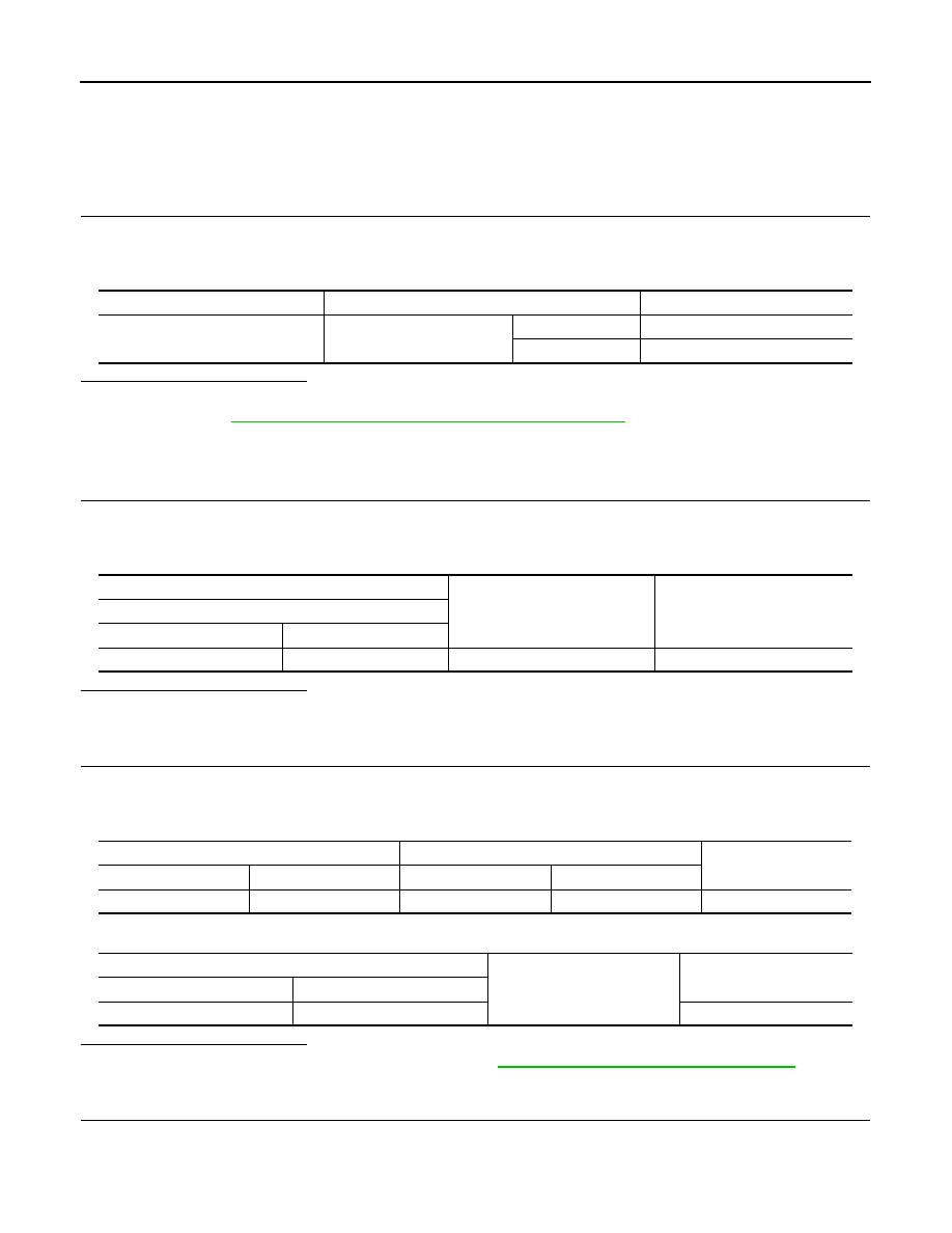
Monitor item
Condition
Status
KNOB LCK SW L
Sliding door LH
LOCK
OFF
UNLOCK
ON
(+)
(–)
Voltage
Sliding door lock status switch LH
Connector
Terminal
D119
1
Ground
8 – 16 V
Sliding door control unit LH
Sliding door lock status switch LH
Continuity
Connector
Terminal
Connector
Terminal
B45
3
D119
1
Existed
Sliding door control unit LH
Ground
Continuity
Connector
Terminal
B45
3
Not existed