Nissan Quest E52. Manual - part 351
DLK-118
< ECU DIAGNOSIS INFORMATION >
SLIDING DOOR CONTROL UNIT
2
(BR)
Ground
Sliding door open/
close switch (rear RH)
Input
Sliding door
open/close
switch (rear RH)
Released
8 – 16 V
Pressed
0 – 1.5 V
3
(L)
Ground
Sliding door lock sta-
tus switch
Input
Sliding door lock
knob RH
Unlock
0 – 1.5 V
Lock
8 – 16 V
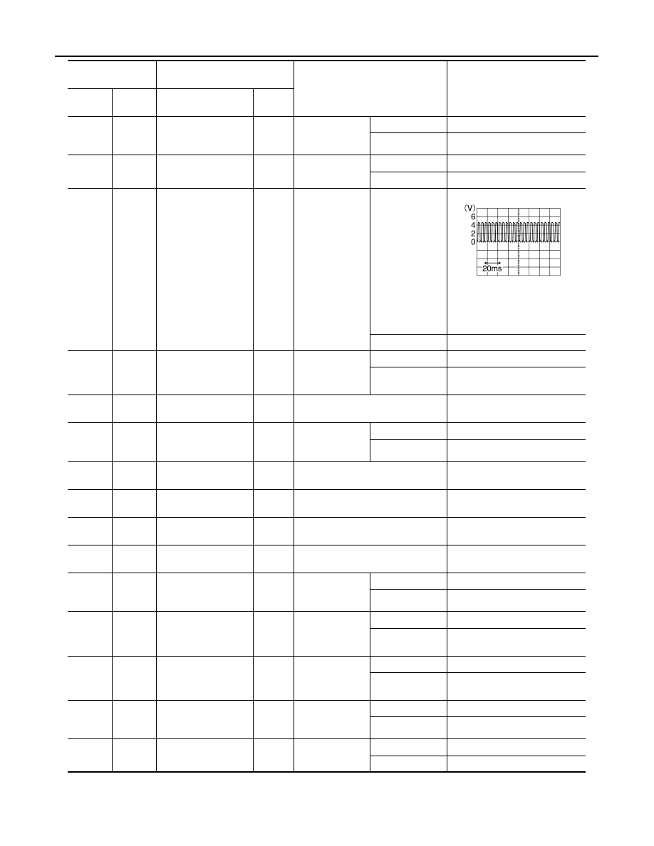
4
(R)
Ground
Encoder A signal
Input
Sliding door RH
Moving (auto or
manual)
NOTE:
Waveform width changes ac-
cording to sliding door open/
close speed
When stopped
4 V or 0 – 0.5 V
5
(GR)
Ground
Half latch switch
Input
Sliding door RH
Open
0 – 1.5 V
Full closed/half
latch
8 – 16 V
6
(LG)
Ground
Power supply (IGN)
Input
Ignition switch ON
9 – 16 V
8
(BR)
Ground
Automatic sliding
door warning buzzer
Output
Automatic slid-
ing door warning
buzzer RH
Sounding
0 – 1.5 V
Not sounding
8 – 16 V
9
(P)
Ground
CAN - L
Input/
Output
—
—
10
(L)
Ground
CAN - H
Input/
Output
—
—
11
(G)
Ground
Encoder power sup-
ply
Output
Ignition switch OFF
8 – 16 V
12
(O)
Ground
Power supply (BAT)
Input
Ignition switch OFF
8 – 16 V
14
(SB)
Ground
Sliding door one-
touch open/close
switch
Output
Sliding door one-
touch open/
close switch RH
Released
8 – 16 V
Pressed
0 – 1.5 V
15
(V)
Ground
Neutral switch
Input
Sliding door clo-
sure motor
Neutral position
8 – 16 V
Other than
above
0 – 1.5 V
18
(W)
Ground
Half latch switch
Input
Sliding door RH
Full closed
8 – 16 V
Other than
above
0 – 1.5 V
19
(GR)
Ground
Sliding door open/
close switch (front
side)
Input
Sliding door
open/close
switch (front RH)
Released
8 – 16 V
Pressed
0 – 1.5 V
20
(LG)
Ground
Child lock status
switch
Input
Child lock
Unlock
0 – 1.5 V
Lock
8 – 16 V
Terminal No.
(Wire color)
Description
Condition
Voltage
(+)
(–)
Signal name
Input/
Output
JMKIA6157ZZ