Nissan Quest E52. Manual - part 278
CHG
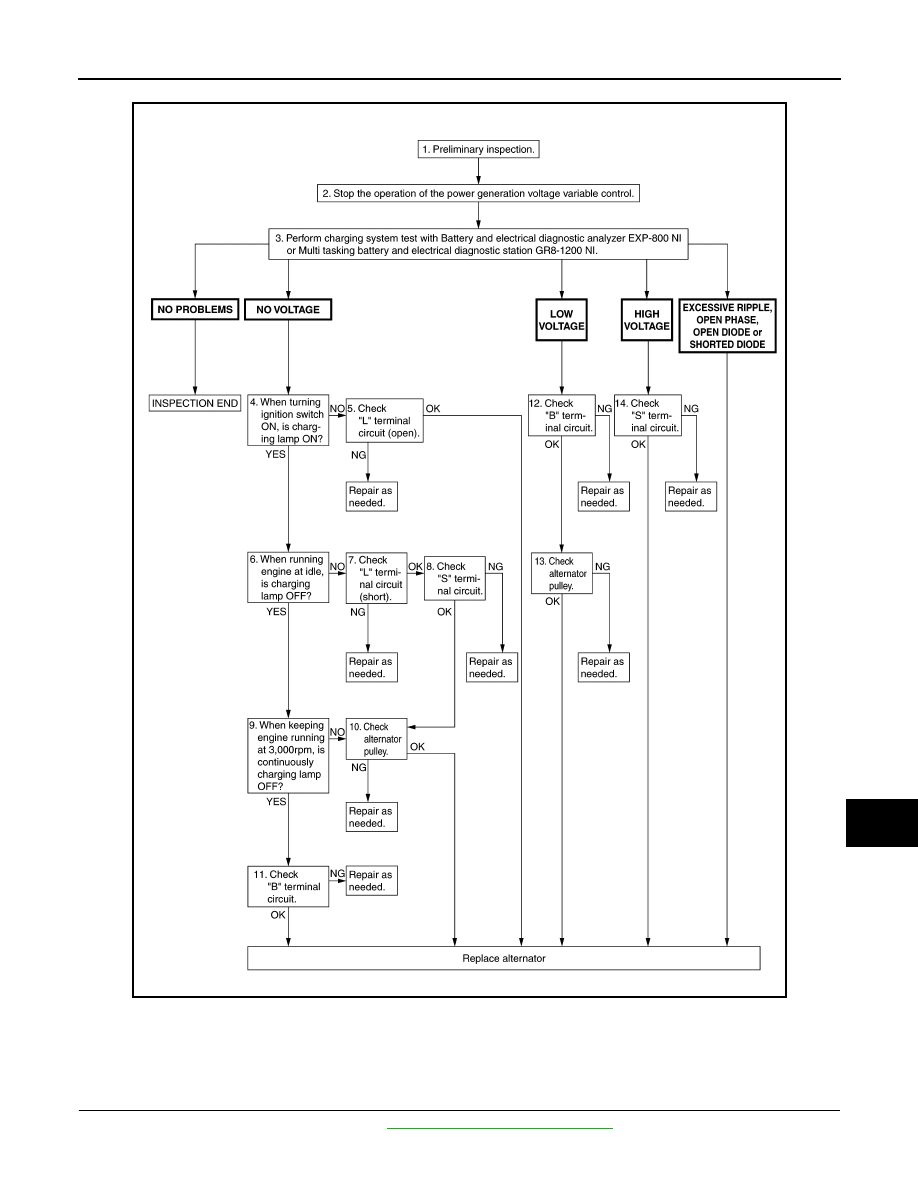
DIAGNOSIS AND REPAIR WORK FLOW
CHG-15
< BASIC INSPECTION >
C
D
E
F
G
H
I
J
K
L
B
A
O
P
N
OVERALL SEQUENCE
DETAILED FLOW
NOTE:
To ensure a complete and thorough diagnosis, the battery, starter and alternator test segments must be done
as a set from start to finish.
1.
PRELIMINARY INSPECTION
Perform the preliminary inspection. Refer to
CHG-21, "Inspection Procedure"
.
JMMIA1147GB