Nissan Quest E52. Manual - part 192
BCS
SYSTEM
BCS-11
< SYSTEM DESCRIPTION >
C
D
E
F
G
H
I
J
K
L
B
A
O
P
N
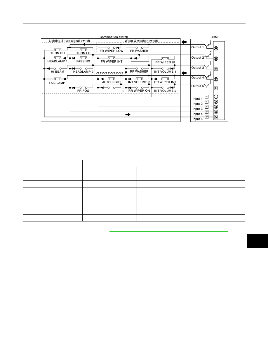
• The circuits between OUTPUT 1 and INPUT 5 and between OUTPUT 4 and INPUT 5 are formed when the
TURN RH switch and TAIL LAMP switch are turned ON.
• BCM detects the combination switch status signal “5AD” when the signals of OUTPUT 1 and OUTPUT 4 are
input to INPUT 5.
• BCM judges that the TURN RH switch and TAIL LAMP switch are ON when the signal “5AD” is detected.
WIPER INTERMITTENT DIAL POSITION
BCM judges the wiper intermittent dial 1 - 7 by the status of INT VOLUME 1, 2 and 3 switches.
NOTE:
For details of wiper intermittent dial position, refer to
WW-8, "FRONT WIPER AND WASHER SYSTEM : System Description"
.
SIGNAL BUFFER SYSTEM
JPMIA1546GB
Wiper intermittent
dial position
Switch status
INT VOLUME 1
INT VOLUME 2
INT VOLUME 3
1
ON
ON
ON
2
ON
ON
OFF
3
ON
OFF
OFF
4
OFF
OFF
OFF
5
OFF
OFF
ON
6
OFF
ON
ON
7
OFF
ON
OFF