Nissan Quest E52. Manual - part 190


  Index      Nissan     Nissan Quest E52 (2011-2014 year) - Service and Repair Manual


Search            


Content   ..  188  189  190  191   ..


Nissan Quest E52. Manual - part 190


BCS

PRECAUTIONS

BCS-3

< PRECAUTION >

C

D

E

F

G

H

I

J

K

L

B

A

O

P

N

PRECAUTION

PRECAUTIONS

Precaution for Supplemental Restraint System (SRS) "AIR BAG" and "SEAT BELT 
PRE-TENSIONER"

INFOID:0000000009651680

The Supplemental Restraint System such as “AIR BAG” and “SEAT BELT PRE-TENSIONER”, used along
with a front seat belt, helps to reduce the risk or severity of injury to the driver and front passenger for certain
types of collision. This system includes seat belt switch inputs and dual stage front air bag modules. The SRS
system uses the seat belt switches to determine the front air bag deployment, and may only deploy one front
air bag, depending on the severity of a collision and whether the front occupants are belted or unbelted.
Information necessary to service the system safely is included in the “SRS AIR BAG” and “SEAT BELT” of this
Service Manual.

WARNING:

Always observe the following items for preventing accidental activation.
• To avoid rendering the SRS inoperative, which could increase the risk of personal injury or death in

the event of a collision that would result in air bag inflation, all maintenance must be performed by
an authorized NISSAN/INFINITI dealer.

• Improper maintenance, including incorrect removal and installation of the SRS, can lead to personal

injury caused by unintentional activation of the system. For removal of Spiral Cable and Air Bag
Module, see “SRS AIR BAG”.

• Never use electrical test equipment on any circuit related to the SRS unless instructed to in this Ser-

vice Manual. SRS wiring harnesses can be identified by yellow and/or orange harnesses or harness
connectors.

PRECAUTIONS WHEN USING POWER TOOLS (AIR OR ELECTRIC) AND HAMMERS

WARNING:

Always observe the following items for preventing accidental activation.
• When working near the Air Bag Diagnosis Sensor Unit or other Air Bag System sensors with the

ignition ON or engine running, never use air or electric power tools or strike near the sensor(s) with
a hammer. Heavy vibration could activate the sensor(s) and deploy the air bag(s), possibly causing
serious injury.

• When using air or electric power tools or hammers, always switch the ignition OFF, disconnect the

battery, and wait at least 3 minutes before performing any service.

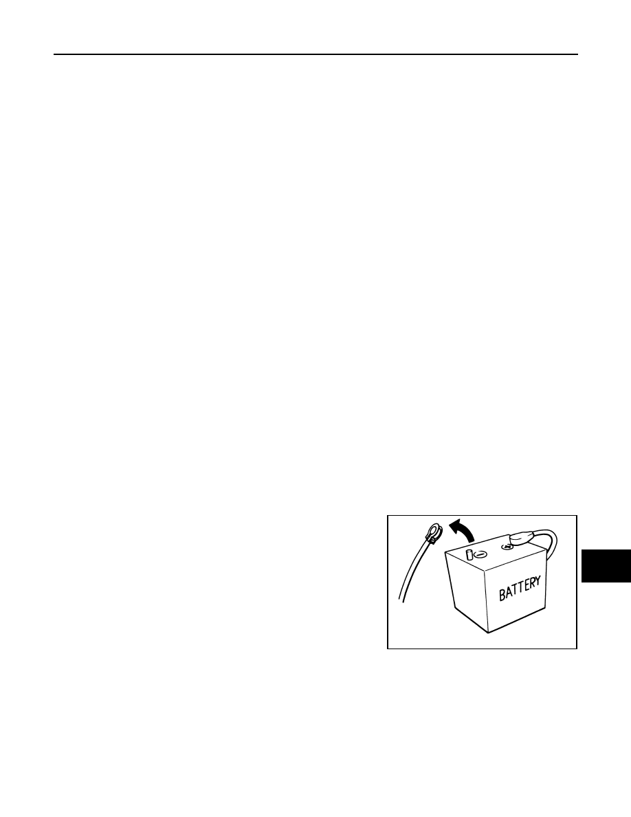
Precautions for Removing Battery Terminal

INFOID:0000000009980276

•  When removing the 12V battery terminal, turn OFF the ignition

switch and wait at least 30 seconds.
NOTE:
ECU may be active for several tens of seconds after the ignition
switch is turned OFF. If the battery terminal is removed before ECU
stops, then a DTC detection error or ECU data corruption may
occur.

•  For vehicles with the 2-batteries, be sure to connect the main bat-

tery and the sub battery before turning ON the ignition switch.
NOTE:
If the ignition switch is turned ON with any one of the terminals of
main battery and sub battery disconnected, then DTC may be
detected.

•  After installing the 12V battery, always check "Self Diagnosis Result" of all ECUs and erase DTC.

NOTE:
The removal of 12V battery may cause a DTC detection error.

SEF289H

BCS-4

< SYSTEM DESCRIPTION >

COMPONENT PARTS

SYSTEM DESCRIPTION

COMPONENT PARTS

BODY CONTROL SYSTEM

BODY CONTROL SYSTEM : Component Parts Location

INFOID:0000000009651681

POWER CONSUMPTION CONTROL SYSTEM

POWER CONSUMPTION CONTROL SYSTEM : Component Parts Location

INFOID:0000000009651682

1.

BCM

A.

Behind of combination meter

JMMIA0856ZZ

1.

Sliding door control unit RH
Refer to 

DLK-23, "AUTOMATIC 

SLIDING DOOR SYSTEM : Compo-
nent Parts Location"

.

2.

Combination meter
Refer to 

MWI-6, "METER SYSTEM : 

Component Parts Location"

.

3.

BCM
Refer to 

BCS-4, "BODY CONTROL 

SYSTEM : Component Parts Loca-
tion"

.

JMMIA0857ZZ

BCS

COMPONENT PARTS

BCS-5

< SYSTEM DESCRIPTION >

C

D

E

F

G

H

I

J

K

L

B

A

O

P

N

4.

IPDM E/R
Refer to 

PCS-4, "IPDM E/R : Com-

ponent Parts Location"

.

5.

Driver seat control unit
Refer to 

ADP-5, "Component Parts 

Location"

.

6.

Sliding door control unit LH
Refer to 

DLK-23, "AUTOMATIC 

SLIDING DOOR SYSTEM : Compo-
nent Parts Location"

.

7.

Automatic back door control module
Refer to 

DLK-22, "AUTOMATIC 

BACK DOOR SYSTEM : 
Component Parts Location"

.

BCS-6

< SYSTEM DESCRIPTION >

SYSTEM

SYSTEM

BODY CONTROL SYSTEM

BODY CONTROL SYSTEM : System Description

INFOID:0000000009651683

OUTLINE

• BCM (Body Control Module) controls the various electrical components. It inputs the information required to

the control from CAN communication and the signal received from each switch and sensor. 

• BCM has combination switch reading function for reading the operation status of combination switches (light,

turn signal, wiper and washer) in addition to a function for controlling the operation of various electrical com-
ponents. It also has the signal transmission function as the passed point of signal and the power saving con-
trol function that reduces the power consumption with the ignition switch OFF.

• BCM is equipped with the diagnosis function that performs the diagnosis with CONSULT and various set-

tings.

BCM CONTROL FUNCTION LIST

System

Reference

Combination switch reading system

BCS-8, "COMBINATION SWITCH READING SYSTEM : System 
Description"

Signal buffer system

BCS-12, "SIGNAL BUFFER SYSTEM : System Description"

Power consumption control system

BCS-13, "POWER CONSUMPTION CONTROL SYSTEM : Sys-
tem Description"

Headlamp system

EXL-12, "HEADLAMP SYSTEM : System Description"

 (Xenon 

type headlamp)

EXL-124, "HEADLAMP SYSTEM : System Description"

 (Halo-

gen type headlamp)

Auto light system

• Xenon type headlamp models
-

EXL-14, "AUTO LIGHT SYSTEM (EXCEPT FOR CANADA) : 
System Description"

 (Except for Canada)

-

EXL-17, "AUTO LIGHT SYSTEM (FOR CANADA) : System 
Description"

 (For Canada)

• Halogen type headlamp models
-

EXL-14, "AUTO LIGHT SYSTEM (EXCEPT FOR CANADA) : 
System Description"

 (Except for Canada)

-

EXL-129, "AUTO LIGHT SYSTEM (FOR CANADA) : System 
Description"

 (For Canada)

Daytime running light system

EXL-20, "DAYTIME RUNNING LIGHT SYSTEM : System De-
scription"

 (Xenon type headlamp)

EXL-132, "DAYTIME RUNNING LIGHT SYSTEM : System De-
scription"

 (Halogen type headlamp)

Turn signal and hazard warning lamp system

EXL-22, "TURN SIGNAL AND HAZARD WARNING LAMP 
SYSTEM : System Description"

 (Xenon type headlamp)

EXL-134, "TURN SIGNAL AND HAZARD WARNING LAMP 
SYSTEM : System Description"

 (Halogen type headlamp)

Parking, license plate, side maker and tail lamps system

EXL-23, "PARKING, LICENSE PLATE, SIDE MARKER AND 
TAIL LAMP SYSTEM : System Description"

 (Xenon type head-

lamp)

EXL-135, "PARKING, LICENSE PLATE, SIDE MARKER AND 
TAIL LAMP SYSTEM : System Description"

 (Halogen type 

headlamp)

Front fog lamp system

EXL-26, "FRONT FOG LAMP SYSTEM : System Description"


(Xenon type headlamp)

EXL-138, "FRONT FOG LAMP SYSTEM : System Descrip-
tion"

 (Halogen type headlamp)

Exterior lamp battery saver system

EXL-28, "EXTERIOR LAMP BATTERY SAVER SYSTEM : 
System Description"

 (Xenon type headlamp)

EXL-140, "EXTERIOR LAMP BATTERY SAVER SYSTEM : 
System Description"

 (Halogen type headlamp)


Content   ..  188  189  190  191   ..