Nissan Quest E52. Manual - part 1240


  Index      Nissan     Nissan Quest E52 (2011-2014 year) - Service and Repair Manual


Search            


Content   ..  1238  1239  1240  1241   ..


Nissan Quest E52. Manual - part 1240


VTL-10

< REMOVAL AND INSTALLATION >

DUCT AND GRILLE

Install in the reverse order of removal.

SIDE VENTILATOR GRILLE

SIDE VENTILATOR GRILLE : Removal and Installation

INFOID:0000000009650638

REMOVAL

1.

Remove instrument panel assembly. Refer to 

IP-14, "Removal and Installation"

.

2.

Remove fixing screw (passenger side only).

3.

Disengage fixing pawls and metal clips, and then remove side ventilator grille.

INSTALLATION

Install in the reverse order of removal.

SIDE DEFROSTER GRILLE

SIDE DEFROSTER GRILLE : Removal and Installation

INFOID:0000000009650639
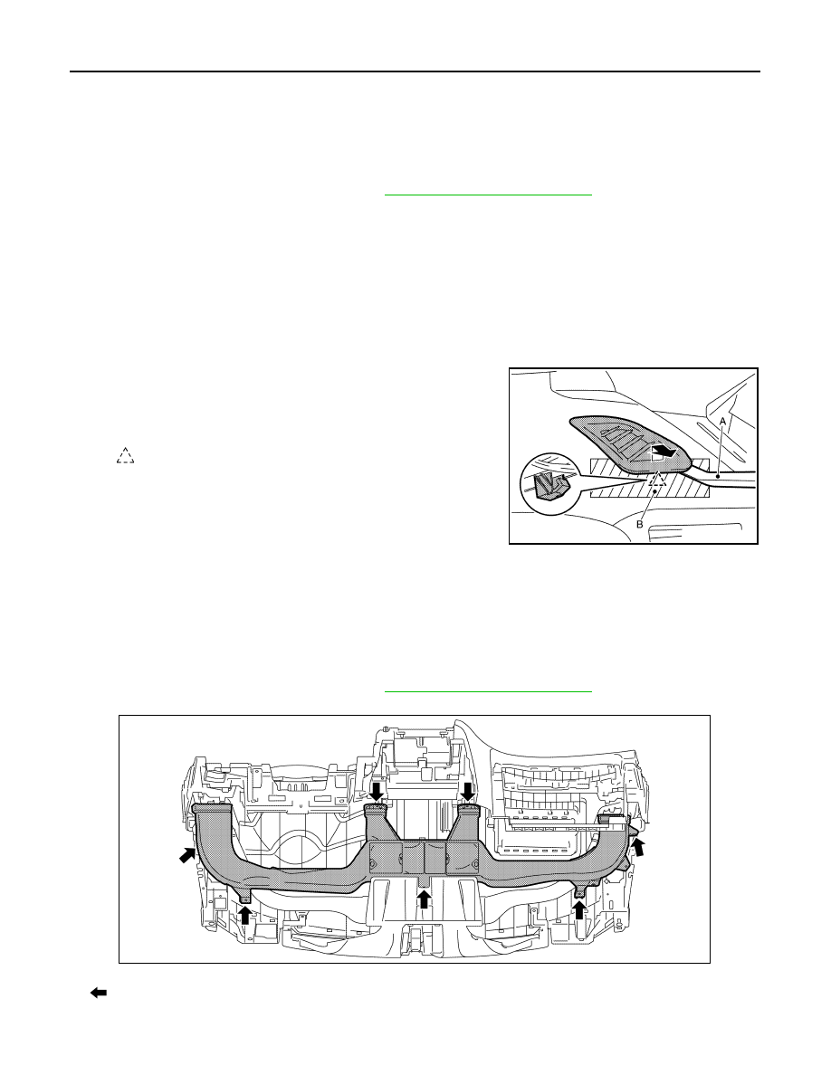
REMOVAL

Disengage fixing pawl using a remover tool (A), and then remove
side defroster grille.

CAUTION:

Apply protective tape (B) on the part to protect it from damage.

INSTALLATION

Install in the reverse order of removal.

CENTER VENTILATOR DUCT

CENTER VENTILATOR DUCT : Removal and Installation

INFOID:0000000009650640

REMOVAL

1.

Remove instrument panel assembly. Refer to 

IP-14, "Removal and Installation"

.

2.

Remove fixing screws, and then remove center ventilator duct.

INSTALLATION

: Pawl

JMIIA1155ZZ

: Screw

JMIIA1800ZZ

DUCT AND GRILLE

VTL-11

< REMOVAL AND INSTALLATION >

C

D

E

F

G

H

J

K

L

M

A

B

VTL

N

O

P

Install in the reverse order of removal.

FRONT DEFROSTER NOZZLE

FRONT DEFROSTER NOZZLE : Removal and Installation

INFOID:0000000009650641

REMOVAL

1.

Remove instrument panel assembly. Refer to 

IP-14, "Removal and Installation"

.

2.

Remove center ventilator duct. Refer to 

VTL-10, "CENTER VENTILATOR DUCT : Removal and Installa-

tion"

.

3.

Remove side defroster nozzle LH and RH. Refer to 

VTL-11, "SIDE DEFROSTER NOZZLE : Removal and

Installation"

.

4.

Remove fixing screw (A), and then remove instrument panel
center bracket (1).

5.

Remove fixing screws (B), and then remove front defroster noz-
zle (2).

INSTALLATION

Install in the reverse order of removal.

SIDE DEFROSTER NOZZLE

SIDE DEFROSTER NOZZLE : Removal and Installation

INFOID:0000000009650642

REMOVAL

Driver Side

1.

Remove instrument panel assembly. Refer to 

IP-14, "Removal and Installation"

.

2.

Remove fixing screws (A), and then remove instrument panel
bracket LH (1).

3.

Remove fixing screw (B), and then remove side defroster nozzle
LH (2).

Passenger Side

1.

Remove instrument panel assembly. Refer to 

IP-14, "Removal and Installation"

.

2.

Remove fixing screws (A), and then remove instrument panel
bracket RH (1).

3.

Remove fixing screw (B), and then remove side defroster nozzle
RH (2).

JMIIA1801ZZ

JMIIA1802ZZ

JMIIA1803ZZ

VTL-12

< REMOVAL AND INSTALLATION >

DUCT AND GRILLE

INSTALLATION

Install in the reverse order of removal.

FRONT FLOOR DUCT 1

FRONT FLOOR DUCT 1 : Removal and Installation

INFOID:0000000009650643

REMOVAL

Driver Side

1.

Remove instrument lower cover LH. Refer to 

IP-14, "Removal and Installation"

.

2.

Remove front floor duct 1 LH.

Passenger Side

1.

Remove instrument lower cover RH. Refer to 

IP-14, "Removal and Installation"

.

2.

Remove harness fixing clip (A), and then remove front floor duct
1 RH.

INSTALLATION

Install in the reverse order of removal.

FRONT FLOOR DUCT 2

FRONT FLOOR DUCT 2 : Removal and Installation

INFOID:0000000009650644

REMOVAL

1.

Pull up front of front floor carpet to secure work space. Refer to 

INT-30, "FRONT FLOOR CARPET :

Removal and Installation"

.

2.

Remove front floor spacer. Refer to 

INT-30, "Exploded View"

.

3.

Remove fixing screws (A) and harness clips (B), and then
remove front floor duct 2.

INSTALLATION

Install in the reverse order of removal.

FOOT DUCT

FOOT DUCT : Removal and Installation

INFOID:0000000009650645

REMOVAL

Driver Side

1.

Remove instrument lower cover LH. Refer to 

IP-14, "Removal and Installation"

.

JMIIA1804ZZ

JMIIA1160ZZ

DUCT AND GRILLE

VTL-13

< REMOVAL AND INSTALLATION >

C

D

E

F

G

H

J

K

L

M

A

B

VTL

N

O

P

2.

Remove fixing screws (A), and then remove foot duct LH (1) and
aspirator (2) from heater & cooling unit assembly as a set.

Passenger Side

1.

Remove heater & cooling unit assembly. Refer to 

HA-49, "HEATER  & COOLING UNIT ASSEMBLY :

Removal and Installation"

.

2.

Remove fixing screws (A), and then remove foot duct RH from
heater & cooling unit assembly.

INSTALLATION

Install in the reverse order of removal.

REAR VENTILATOR GRILLE

REAR VENTILATOR GRILLE : Removal and Installation

INFOID:0000000009650646

REMOVAL

Disengage fixing metal clips using a remover tool (A), and then
remove rear ventilator grille.

INSTALLATION

Install in reverse order of removal.

REAR FOOT DUCT

REAR FOOT DUCT : Removal and Installation

INFOID:0000000009650647

REMOVAL

1.

Remove luggage side lower finisher RH. Refer to 

INT-43, "LUGGAGE SIDE LOWER FINISHER :

Removal and Installation"

.

JMIIA1805ZZ

JMIIA1806ZZ

: Metal clip

JMIIA1185ZZ


Content   ..  1238  1239  1240  1241   ..