Content .. 1232 1233 1234 1235 ..
Nissan Quest E52. Manual - part 1234
TM-166
< REMOVAL AND INSTALLATION >
[CVT: RE0F09B]
WATER HOSE
WATER HOSE
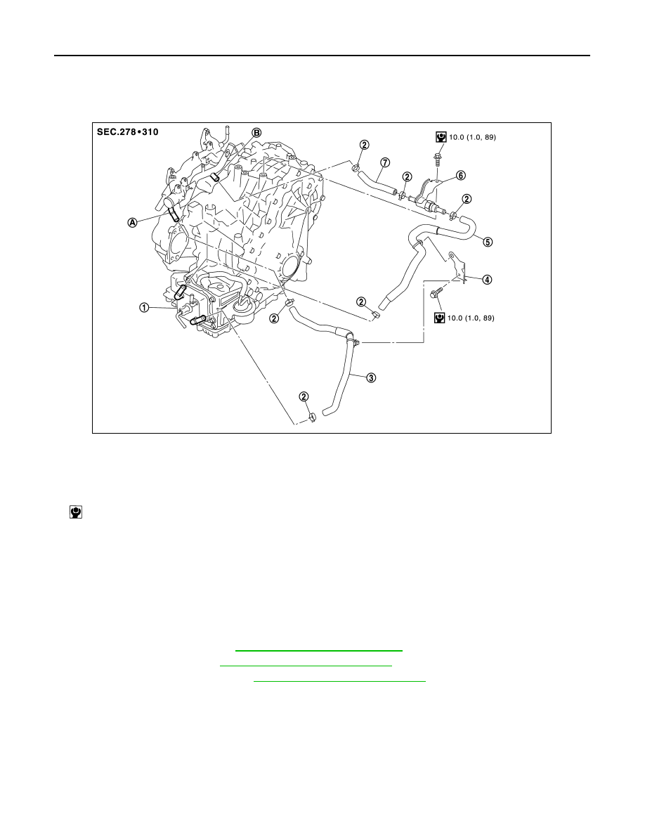
Exploded View
INFOID:0000000009650243
Removal and Installation
INFOID:0000000009650244
REMOVAL
WARNING:
Never remove the radiator cap when the engine is hot. Serious burns could occur from high pressure
coolant escaping from the radiator.
CAUTION:
Perform these steps after the coolant temperature has cooled sufficiently.
1.
Remove air duct (inlet). Refer to
EM-26, "Removal and Installation"
2.
Remove the battery. Refer to
PG-105, "Removal and Installation"
.
3.
Remove ECM and bracket. Refer to
EC-460, "Removal and Installation"
4.
Remove hose clamp, and then remove water hoses.
5.
Remove heater thermostat.
6.
Remove bracket.
INSTALLATION
Note the following, and Install in the reverse order of removal.
CAUTION:
Install clips of water hose A/B to bracket.
1.
CVT oil warmer
2.
Hose clamp
3.
Water hose A
4.
Bracket
5.
Water hose B
6.
Heater thermostat
7.
Water hose C
A.
Water outlet
B.
Heater pipe
: N·m (kg-m, in-lb)
JSDIA2322GB