Nissan Quest E52. Manual - part 1013


  Index      Nissan     Nissan Quest E52 (2011-2014 year) - Service and Repair Manual


Search            


Content   ..  1011  1012  1013  1014   ..


Nissan Quest E52. Manual - part 1013


NOISE, VIBRATION AND HARSHNESS (NVH) TROUBLESHOOTING

RAX-3

< SYMPTOM DIAGNOSIS >

C

E

F

G

H

I

J

K

L

M

A

B

RAX

N

O

P

SYMPTOM DIAGNOSIS

NOISE, VIBRATION AND HARSHNESS (NVH) TROUBLESHOOTING

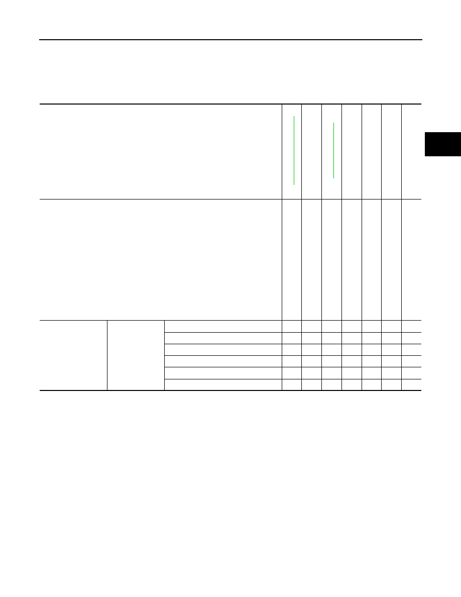
NVH Troubleshooting Chart

INFOID:0000000009650473

Use chart below to find the cause of the symptom. If necessary, repair or replace these parts.

×

: Applicable

Reference

RAX

-5, "

Ex

pl

od

ed

 V

iew

"

RAX-4, "

In

sp

ec

ti

o

n

"

NVH 

in 

RAX and RSU sections

NVH in WT section

NVH in WT section

NVH in BR section

Possible cause and SUSPECTED PARTS

Im

p

rop

er i

n

s

ta

lla

tio

n

lo

os

en

es

s

P

a

rt

s interference

W

he

el be

arin

g da

ma

ge

REA

R

 AXLE AND REAR S

U

SPENSION

TI

RE

ROAD W

H

EEL

BR

AK

E

Symptom

REAR AXLE

Noise

×

×

×

×

×

×

×

Shake

×

×

×

×

×

×

×

Vibration

×

×

×

×

×

Shimmy

×

×

×

×

×

×

Judder

×

×

×

×

×

Poor quality ride or handling

×

×

×

×

×

RAX-4

< PERIODIC MAINTENANCE >

REAR WHEEL HUB

PERIODIC MAINTENANCE

REAR WHEEL HUB

Inspection

INFOID:0000000009650474

COMPONENT PART

Check the mounting conditions (looseness, back lash) of each component and component conditions (wear,
damage) are normal.

WHEEL HUB ASSEMBLY (BEARING-INTEGRATED TYPE)

Check the following items, and replace the part it necessary.
• Move wheel hub assembly in the axial direction by hand. Check there is no looseness of wheel bearing. 

• Rotate wheel hub assembly and check there is no unusual noise or other irregular conditions. If there is any

of irregular conditions, replace wheel hub assembly.

Axial end play

: Refer to 

RAX-8, "Wheel Bearing"

.

REAR WHEEL HUB AND HOUSING

RAX-5

< REMOVAL AND INSTALLATION >

C

E

F

G

H

I

J

K

L

M

A

B

RAX

N

O

P

REMOVAL AND INSTALLATION

REAR WHEEL HUB AND HOUSING

Exploded View

INFOID:0000000009650475

Except for 3.5LE Grade

For 3.5LE Grade

1.

Axle housing

2.

Bushing

3.

Cotter pin

4.

Hub cap

5.

Parking brake shoe assembly

6.

Hub bolt

7.

Wheel hub assembly (Bearing-inte-
grated type)     

8.

Disc rotor

9.

Plug

: N·m (kg-m, ft-lb)

: Always replace after every disassembly.

JSDIA2758GB

1.

Ball seat

2.

Axle housing

3.

Bushing

4.

Cotter pin

5.

Hub cap

6.

Parking brake shoe assembly

JSDIA2759GB

RAX-6

< REMOVAL AND INSTALLATION >

REAR WHEEL HUB AND HOUSING

Removal and Installation

INFOID:0000000009650476

REMOVAL

1.

Remove tires with power tool. Refer to 

WT-46, "Exploded View"

.

2.

Remove wheel sensor. Refer to 

BRC-120, "REAR WHEEL SENSOR : Removal and Installation"

.

3.

Remove caliper assembly. Hang caliper assembly in a place where it will not interfere with work. Refer to

BR-47, "BRAKE CALIPER ASSEMBLY : Removal and Installation"

.

CAUTION:

Never depress brake pedal while brake caliper is removed. 

4.

Remove disc rotor. If disc rotor cannot be removed, remove as follows.

CAUTION:

• Parking brake completely in the released position.
• Put matching marks (A) on the wheel hub assembly and

the disc rotor before removing the disc rotor.

• Never drop disc rotor.

a.

Fix the disc rotor with wheel nuts and remove the adjusting hole
plug.

b.

Using suitable tool, rotate adjuster (1) in the direction (B) to
retract and loosen brake shoe.

5.

Remove wheel hub assembly.

6.

Remove parking brake and rear cable from back plate.
• Parking brake: Refer to 

PB-8, "Removal and Installation"

.

• Rear cable: Refer to 

PB-6, "Removal and Installation"

.

7.

Remove radius rod from axle housing. Refer to 

RSU-13,

"Exploded View"

.

8.

Remove rear lower link and coil spring. Refer to 

RSU-8,

"Removal and Installation"

.

9.

Set suitable jack under axle housing.

CAUTION:

• At this step, the jack must be set only for supporting the removal procedure. For details on jack-

ing up the vehicle, refer to 

GI-29, "Garage Jack and Safety Stand and 2-Pole Lift"

.

• Never damage the axle housing with a jack.
• Check the stable condition when using a jack.

10. Remove front lower link from shock absorber with power tool. Refer to 

RSU-10, "Exploded View"

.

11. Remove front lower link from axle housing. Refer to 

RSU-15, "Exploded View"

.

12. Remove cotter pin, then remove suspension arm mounting nut.

13. Separate suspension arm from axle housing, using ball joint remover (commercial service tool), and then

remove axle housing.

CAUTION:

• Never damage ball joint boot.
• Temporarily tighten nuts to prevent damage to threads and to prevent the ball joint remover from

coming off.

7.

Hub bolt

8.

Wheel hub assembly (Bearing-inte-
grated type)     

9.

Disc rotor

10. Plug

: N·m (kg-m, ft-lb)

: Always replace after every disassembly.

JSDIA2721ZZ

JPFIB0007ZZ


Content   ..  1011  1012  1013  1014   ..