Nissan Quest E52. Manual - part 1009


  Index      Nissan     Nissan Quest E52 (2011-2014 year) - Service and Repair Manual


Search            


Content   ..  1007  1008  1009  1010   ..


Nissan Quest E52. Manual - part 1009


PWO-24

< DTC/CIRCUIT DIAGNOSIS >

[AC 120 V OUTLET]

AC 120 V OUTLET MAIN SWITCH POWER SUPPLY CIRCUIT

AC 120 V OUTLET MAIN SWITCH POWER SUPPLY CIRCUIT

Diagnosis Procedure

INFOID:0000000009651884

1.

CHECK FUSE

Check that the following fuse is not blown.

Is the fuse fusing?

YES

>> Replace the blown fuse after repairing the affected circuit if a fuse is blown.

NO

>> GO TO 2.

2.

CHECK POWER SUPPLY FOR AC 120 V OUTLET MAIN SWITCH

1.

Turn ignition switch ON.

2.

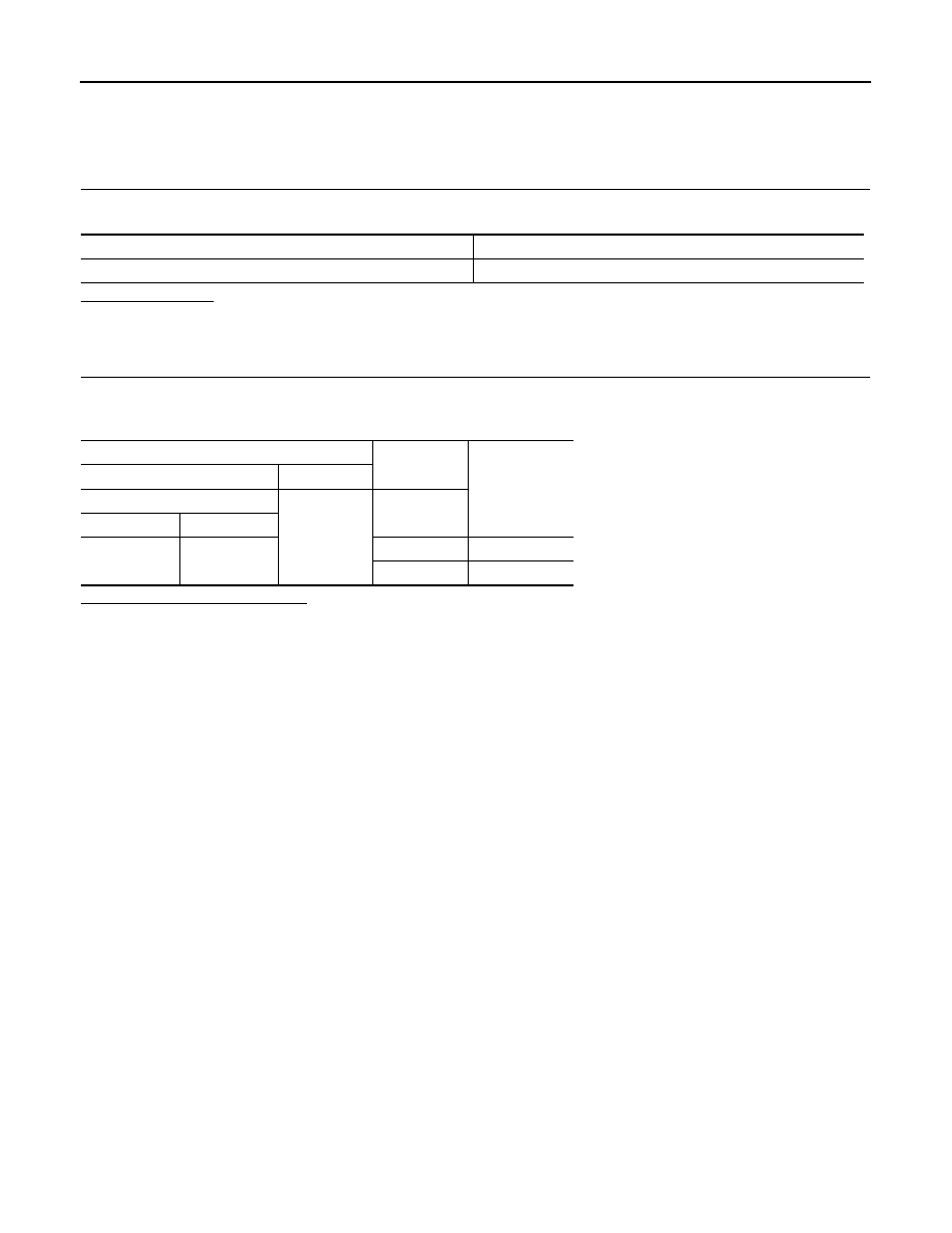
Check for voltage between the AC 120 V main switch harness connector and ground.

Is the inspection result normal?

YES

>> INSPECTION END

NO

>> Repair the AC 120 V main switch power supply circuit.

Signal name

Fuse No.

Ignition power supply

3

Terminals

Condition

Voltage

(Approx.)

(+)

(–)

AC 120 V outlet main switch

Ground

Ignition switch

Connector

Terminal

M24

2

OFF

0 V

ON

Battery voltage

PWO

AC 120 V OUTLET MAIN SWITCH INPUT SIGNAL CIRCUIT

PWO-25

< DTC/CIRCUIT DIAGNOSIS >

[AC 120 V OUTLET]

C

D

E

F

G

H

I

J

K

L

B

A

O

P

N

AC 120 V OUTLET MAIN SWITCH INPUT SIGNAL CIRCUIT

Diagnosis Procedure

INFOID:0000000009651885

1.

CHECK HARNESS BETWEEN INVERTER UNIT AND AC 120 V OUTLET MAIN SWITCH

1.

Turn ignition switch OFF.

2.

Disconnect inverter unit connector and AC 120 V outlet main switch connector.

3.

Check for continuity between the inverter unit harness connector and AC 120 V outlet main switch har-
ness connector.

4.

Check for continuity between inverter unit harness connector and ground.

Is the inspection result normal?

YES

>> GO TO 2.

NO

>> Repair the harnesses or connectors.

2.

CHECK AC 120 V OUTLET MAIN SWITCH INPUT SIGNAL

1.

Connect inverter unit connector and AC 120 V outlet main switch connector.

2.

Turn ignition switch ON.

3.

AC 120 V outlet main switch ON.

4.

Check for voltage between the inverter unit harness connector and ground.

Is the inspection result normal?

YES

>> INSPECTION END

NO

>> GO TO 3.

3.

CHECK AC 120 V OUTLET MAIN SWITCH

1.

Turn ignition switch OFF.

2.

Remove AC 120 V outlet main switch.

3.

Check AC 120 V outlet main switch. Refer to 

PWO-25, "Component Inspection"

.

Is the inspection result normal?

YES

>> INSPECTION END

NO

>> Replace AC 120 V outlet main switch.

Component Inspection

INFOID:0000000009651886

1.

CHECK AC 120 V OUTLET MAIN SWITCH

Check continuity of AC 120 V outlet main switch.

Inverter unit

AC 120 V outlet main switch

Continuity

Connector

Terminal

Connector

Terminal

B226

6

M24

3

Existed

Inverter unit

Ground

Continuity

Connector

Terminal

B226

6

Not existed

Terminals

Condition

Voltage

(Approx.)

(+)

(–)

Inverter unit

Ground

AC 120 V out-

let main 

switch

Connector

Terminal

B226

6

OFF

0 V

ON

12 V

PWO-26

< DTC/CIRCUIT DIAGNOSIS >

[AC 120 V OUTLET]

AC 120 V OUTLET MAIN SWITCH INPUT SIGNAL CIRCUIT

Is the inspection result normal?

YES

>> INSPECTION END

NO

>> Replace AC 120 V outlet main switch.

Terminal

Condition

Continuity

1

3

When AC 120 V outlet main switch is ON

Existed

When AC 120 V outlet main switch is OFF

Not existed

PWO

AC 120 V POWER OUTPUT CIRCUIT

PWO-27

< DTC/CIRCUIT DIAGNOSIS >

[AC 120 V OUTLET]

C

D

E

F

G

H

I

J

K

L

B

A

O

P

N

AC 120 V POWER OUTPUT CIRCUIT

Diagnosis Procedure

INFOID:0000000009651887

1.

CHECK HARNESS BETWEEN INVERTER UNIT AND AC 120 V OUTLET

1.

Turn ignition switch OFF.

2.

Disconnect inverter unit connector and AC 120 V outlet connector.

3.

Check for continuity between the inverter unit harness connector and AC 120 V outlet harness connector.

4.

Check for continuity between inverter unit harness connector and ground.

5.

Check for continuity between inverter unit harness connector.

Is the inspection result normal?

YES

>> GO TO 2.

NO

>> Repair or replace the harnesses or connectors.

2.

CHECK INVERTER UNIT OUTPUT SIGNAL

1.

Connect inverter unit connector and AC 120 V outlet connector. 

2.

Turn ignition switch ON.

3.

AC 120 V outlet main switch ON. (AC 120 V outlet main switch indicator ON)

4.

Check voltage between inverter unit harness connector.

CAUTION:

• To measure AC 120 V output signal, always use the circuit tester AC range.
• Never allow the probes to contact each other.
Is the inspection result normal?

YES

>> GO TO 3

NO

>> Replace inverter unit. 

3.

CHECK AC 120 V OUTLET VOLTAGE

1.

AC 120 V outlet main switch ON. (AC 120 V outlet main switch indicator ON)

2.

Check voltage between AC 120 V outlet.

Inverter unit

AC 120 V outlet

Continuity

Connector

Terminal

Connector

Terminal

B226

5

B271

1

Existed

1

2

Inverter unit

Ground

Continuity

Connector

Terminal

B226

5

Not existed

1

Inverter unit

Continuity

Connector

Terminal

B226

5

1

Not existed

Terminals

Condition

Standard value

Voltage

(Approx.)

(+)

(-)

Inverter unit

Inverter unit

AC 120 V outlet 

main switch

Connector

Terminal

Connector

Terminal

B226

5

B226

1

OFF

Approx. 0 V

0 V

ON

AC 108 – 132 V

AC 120 V


Content   ..  1007  1008  1009  1010   ..