Nissan Quest E52. Manual - part 90
AV
STEERING SWITCH GROUND CIRCUIT
AV-239
< DTC/CIRCUIT DIAGNOSIS >
[BASE AUDIO WITH SEPARATE DISPLAY]
C
D
E
F
G
H
I
J
K
L
M
B
A
O
P
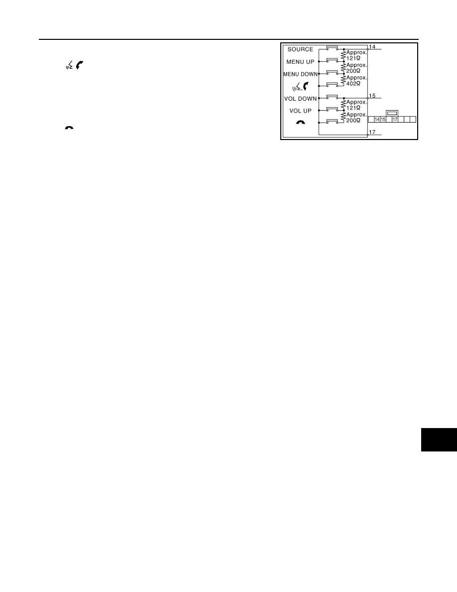
Standard
Between terminals 14 and 17
switch
ON
: 708 – 737
Ω
MENU DOWN switch ON
: 314 – 327
Ω
MENU UP switch ON
: 118 – 123
Ω
SOURCE switch ON
: Less than 1
Ω
Between terminals 15 and 17
switch ON
: 314 – 327
Ω
VOL UP switch ON
: 118 – 123
Ω
VOL DOWN switch ON
: Less than 1
Ω
JSNIA0216GB