Nissan Quest E52. Manual - part 9
DRIVER SEAT CONTROL UNIT
ADP-29
< ECU DIAGNOSIS INFORMATION >
C
D
E
F
G
H
I
K
L
M
A
B
ADP
N
O
P
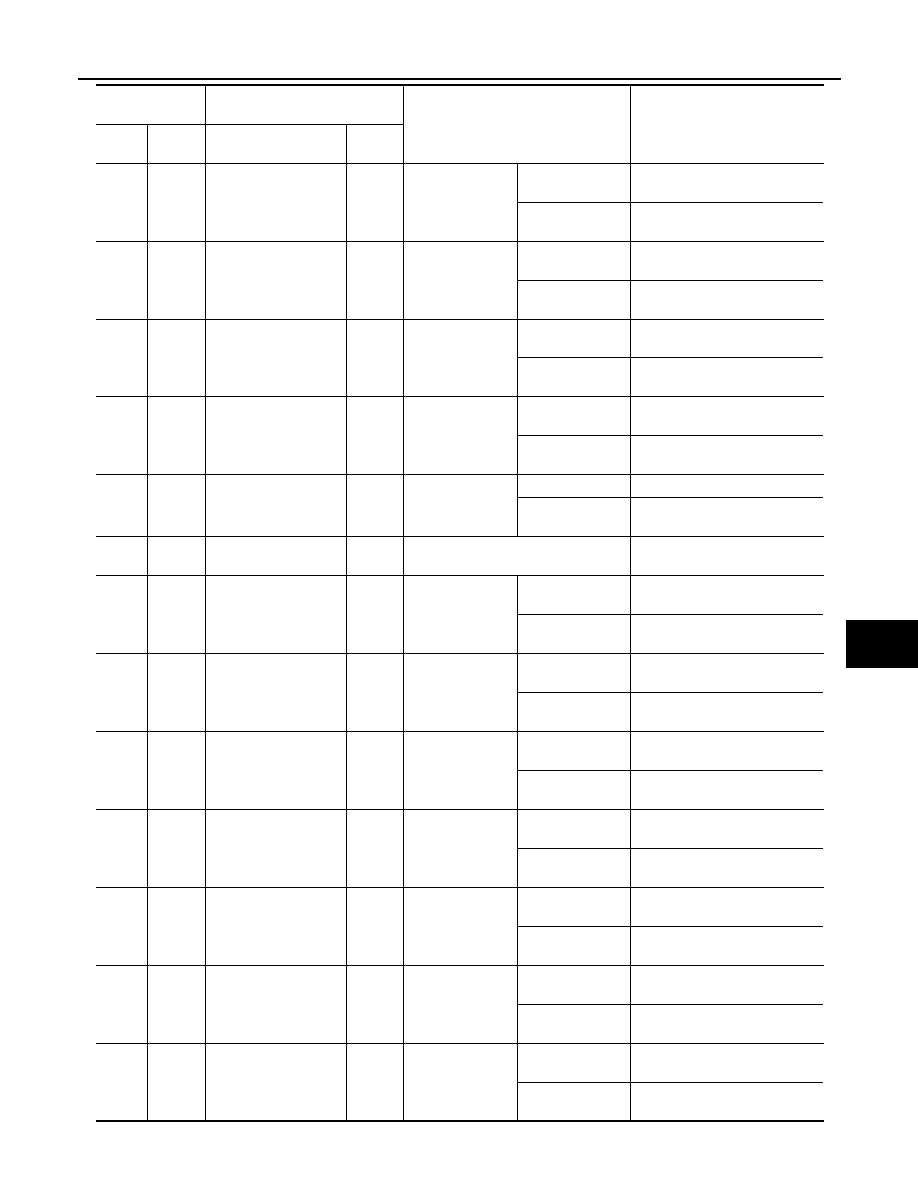
24
(V/W)
Ground
Sliding switch forward
signal
Input
Sliding switch
Operate
(forward)
0 – 1
Other than the
above
9 – 16
25
(Y/B)
Ground
Reclining switch for-
ward signal
Input
Reclining switch
Operate
(forward)
0 – 1
Other than the
above
9 – 16
26
(Y/R)
Ground
Lifting switch (front) up
signal
Input
Lifting switch
(front)
Operate
(up)
0 – 1
Other than the
above
9 – 16
27
(Y/L)
Ground
Lifting switch (rear) up
signal
Input
Lifting switch
(rear)
Operate
(up)
0 – 1
Other than the
above
9 – 16
28
(G)
Ground
Set switch signal
Input
Set switch
Press
0 – 1
Other than the
above
4 – 6
33
(R)
Ground
Battery power supply
Input
—
9 – 16
34
(B)
Ground
Sliding motor back-
ward output signal
Output
Seat sliding
Operate
(backward)
9 – 16
Other than the
above
0 – 1
35
(G)
Ground
Reclining motor for-
ward output signal
Output
Seat reclining
Operate
(forward)
9 – 16
Other than the
above
0 – 1
36
(L)
Ground
Lifting motor (front)
down output signal
Output
Seat lifting (front)
Operate
(down)
9 – 16
Other than the
above
0 – 1
38
(GR)
Ground
Sliding motor forward
output signal
Output
Seat sliding
Operate
(forward)
9 – 16
Other than the
above
0 – 1
39
(Y)
Ground
Reclining motor back-
ward output signal
Output
Seat reclining
Operate
(backward)
9 – 16
Other than the
above
0 – 1
40
(W)
Ground
Lifting motor (front) up
output signal
Output
Seat lifting (front)
Operate
(up)
9 – 16
Other than the
above
0 – 1
41
(V)
Ground
Lifting motor (rear) up
output signal
Output
Seat lifting (rear)
Operate
(up)
9 – 16
Other than the
above
0 – 1
Terminal No.
(Wire color)
Description
Condition
Voltage (V)
+
-
Signal name
Input/
output