Nissan Cube. Manual - part 946


  Index      Nissan     Nissan Cube (2014 year) - Service and Repair Manual


Search            


Content   ..  944  945  946  947   ..


Nissan Cube. Manual - part 946


TM-40

< UNIT DISASSEMBLY AND ASSEMBLY >

[6MT: RS6F94R]

TRANSAXLE ASSEMBLY

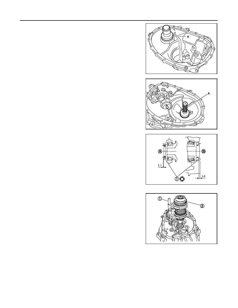
17. Install differential side bearing outer race (transaxle case side)

to transaxle case, using the drift (A) [SST: ST33400001 (J-
26082)].

CAUTION:

Replace differential side bearing outer race (transaxle case
side) and differential side bearing inner race (transaxle case
side) as a set.

18. Install differential side bearing outer race (clutch housing side) to

clutch housing, using the drift (A) [SST: KV38100200 ( - )].

CAUTION:

Replace differential side bearing outer race (clutch housing
side) and differential side bearing inner race (clutch hous-
ing side) as a set.

19. Install differential side oil seals (1) to clutch housing and tran-

saxle case, using the drift [Stamping number: B.vi 1666-B] of the
drift set [SST: KV32500QAA ( - )].

20. Install magnet to clutch housing.

21. Install final drive assembly to clutch housing.

22. Set fork rod (1) to input shaft assembly (2), and then install them

to clutch housing.

PCIB1726E

PCIB1722E

A

: Transaxle case side

B

: Clutch housing side

Dimension “L

1

: 1.2 – 1.8 mm (0.047 – 0.071 in) 

Dimension “L

2

: 2.7 – 3.3 mm (0.106 – 0.130 in)

JPDIC0454ZZ

JPDIC0608ZZ

TRANSAXLE ASSEMBLY

TM-41

< UNIT DISASSEMBLY AND ASSEMBLY >

[6MT: RS6F94R]

C

E

F

G

H

I

J

K

L

M

A

B

TM

N

O

P

23. Install mainshaft assembly (1) according to the following proce-

dures.

a.

Pull up input shaft assembly (2) and fork rod (3).

b.

Set 1st-2nd fork rod (4) to mainshaft assembly, and then install
them to clutch housing.

24. Install reverse idler shaft assembly (1) according to the following

procedures.

a.

Install spring washer to clutch housing.

b.

Pull up input shaft assembly (2), mainshaft assembly (3), fork
rod (4), and 1st-2nd fork rod (5).
NOTE:
It is easier to pull up when shifting each fork rod to each shaft
side.

c.

Set reverse fork rod (6) to reverse idler shaft assembly, and then
install them to clutch housing.

25. Shift 1st-2nd fork rod (1), fork rod (2), and reverse fork rod (3) to

the neutral position.

26. Install selector (4) to clutch housing.

CAUTION:

Replace selector lever and selector as a set.

27. Install selector spring (1) to return bushing (A).

28. Apply recommended sealant to mounting surface of transaxle

case.
• Use Genuine Silicone RTV or an equivalent. Refer to 

GI-22,

"Recommended Chemical Products and Sealants"

.

CAUTION:

• Remove old sealant adhering to the mounting surfaces.

Also remove any moisture, oil, or foreign material adher-
ing to both mounting surfaces.

• Check that mounting surface is not damaged.
• Apply sealant bead continuously.

29. Install transaxle case to clutch housing while rotating shifter

lever A (1) in the direction as shown in the figure.

JPDIC0609ZZ

JPDIC0606ZZ

SCIA7782E

JPDIC0445ZZ

JPDIC0110ZZ

TM-42

< UNIT DISASSEMBLY AND ASSEMBLY >

[6MT: RS6F94R]

TRANSAXLE ASSEMBLY

30. Install reverse idler shaft mounting bolt (

) according to the fol-

lowing procedures.

a.

Install seal washer to reverse idler shaft mounting bolt, and
install reverse idler shaft mounting bolt to transaxle case.

CAUTION:

Never reuse seal washer.

b.

Tighten reverse idler shaft mounting bolt to the specified torque. 

31. Tighten transaxle case mounting bolts (

) to the specified

torque.

32. Install position switch (1) according to the following procedures.

a.

Apply recommended sealant to threads of position switch.
• Use Genuine Silicone RTV or an equivalent. Refer to 

GI-22,

"Recommended Chemical Products and Sealants"

.

CAUTION:

Remove old sealant and oil adhering to threads.

b.

Install position switch to transaxle case, and tighten it to the
specified torque.

33. Install bracket (2) to transaxle case, and tighten mounting bolt to

the specified torque.

34. Install selector lever (3) according to following the procedures.

a.

Install selector lever to transaxle case.

CAUTION:

Replace selector lever and selector as a set.

b.

Install retaining pin to selector lever, using a pin punch.

CAUTION:

Never reuse retaining pin.

35. Install drain plug according to the following procedures.
a.

Install gasket to drain plug.

CAUTION:

Never reuse gasket.

b.

Install drain plug to clutch housing, using a socket [Commercial service tool].

c.

Tighten drain plug to the specified torque.

36. Install filler plug according to the following procedures.

a.

Install gasket to filler plug, and then install them to transaxle case.

CAUTION:

Never reuse gasket.

b.

Tighten filler plug to the specified torque.

CAUTION:

Fill with gear oil before tighten filler plug to the specified torque.

PCIB1695E

PCIB1694E

SCIA7784E

INPUT SHAFT AND GEAR

TM-43

< UNIT DISASSEMBLY AND ASSEMBLY >

[6MT: RS6F94R]

C

E

F

G

H

I

J

K

L

M

A

B

TM

N

O

P

INPUT SHAFT AND GEAR

Exploded View

INFOID:0000000009948884

Disassembly

INFOID:0000000009948885

CAUTION:

• Fix input shaft in a vise with backplate, and then remove gears and snap rings.

1.

Input shaft front bearing

2.

Input shaft

3.

3rd input gear

4.

Spacer

5.

Snap ring

6.

3rd baulk ring

7.

3rd-4th coupling sleeve

8.

3rd-4th synchronizer hub

9.

Insert key

10. 4th baulk ring

11. 4th input gear

12. 5th input gear

13. 5th baulk ring

14. 5th-6th coupling sleeve

15. 5th-6th synchronizer hub

16. 6th baulk ring

17. Needle bearing 

18. 6th input gear

19. Input shaft rear bearing

A.

First step

B.

Final step

: Apply gear oil.

: Replace the parts as a set.

Refer to 

GI-4, "Components"

 for symbols not described on the above.

JPDIC0407GB


Content   ..  944  945  946  947   ..