Nissan Cube. Manual - part 947
 

  Index      Nissan     Nissan Cube (2014 year) - Service and Repair Manual


Search            


Content   ..  945  946  947  948   ..


Nissan Cube. Manual - part 947


TM-44

< UNIT DISASSEMBLY AND ASSEMBLY >

[6MT: RS6F94R]

INPUT SHAFT AND GEAR

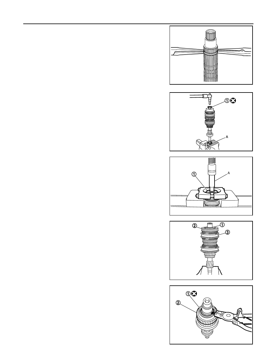
• For removal of snap ring, set snap ring pliers and flat pliers at

both sides of snap ring. While expanding snap ring with snap
ring pliers, move snap ring with flat pliers.

• Disassemble gear components putting direction marks on the

parts that do not affect any functions.

1.

Remove input shaft rear bearing mounting bolt (1), using the
drift (A) [SST: KV32300QAM ( - )].

2.

Remove input shaft rear bearing (1) according to the following
procedures.

a.

Set a puller [Commercial service tool] to input shaft rear bearing.

b.

Remove input shaft rear bearing, using a drift (A) [Commercial
service tool].

3.

Remove spacer (1), 6th input gear (2), needle bearing, 6th baulk
ring, and 5th-6th synchronizer hub assembly (3).

4.

Remove insert keys and 5th-6th coupling sleeve from 5th-6th
synchronizer hub.

5.

Remove snap ring (1).

6.

Remove spacer, 5th baulk ring, 5th input gear (2), and spacer.

SCIA1755J

JPDIC0449ZZ

JPDIC0111ZZ

PCIB1750E

PCIB1754E

INPUT SHAFT AND GEAR

TM-45

< UNIT DISASSEMBLY AND ASSEMBLY >

[6MT: RS6F94R]

C

E

F

G

H

I

J

K

L

M

A

B

TM

N

O

P

7.

Remove snap ring (1).

8.

Remove spacer, 4th input gear (2), 4th baulk ring, and 3rd-4th
synchronizer hub assembly (3).

9.

Remove insert keys and 3rd-4th coupling sleeve from 3rd-4th
synchronizer hub.

10. Remove snap ring (1).
11. Remove spacer, 3rd baulk ring, and 3rd input gear (2).

12. Set a puller [Commercial service tool] to input shaft front bearing

(1), and then remove input shaft front bearing.

Assembly

INFOID:0000000009948886

Note the following procedures, and assemble in the reverse order of disassembly.

CAUTION:

• Replace transaxle assembly when replacing input shaft.
• For installation of snap ring, set snap ring pliers and flat pliers

at both sides of snap ring. While expanding snap ring with
snap ring pliers, move snap ring with flat pliers.

• Never reuse snap ring.
• Check that snap ring is securely installed in a groove.
• Replace 3rd-4th coupling sleeve and 3rd-4th synchronizer

hub as a set.

• Replace 5th-6th coupling sleeve and 5th-6th synchronizer hub

as a set.

PCIB1753E

PCIB1752E

PCIB1751E

SCIA1755J

TM-46

< UNIT DISASSEMBLY AND ASSEMBLY >

[6MT: RS6F94R]

INPUT SHAFT AND GEAR

• Be careful to install 3rd-4th synchronizer hub according to the

specified direction.

• Be careful to install 5th-6th synchronizer hub according to the

specified direction.

• Install input shaft front bearing (1), using a drift (A) [Commercial

service tool].

• Install input shaft rear bearing (1), using a drift (A) [Commercial

service tool] and the drift (B) [SST: ST36720030 ( - )].

• Apply gear oil to 3rd baulk ring, 4th baulk ring, 5th baulk ring, and

6th baulk ring.

A : 3rd input gear side

B : 4th input gear side

PCIB1748E

A : 5th input gear side

B : 6th input gear side

PCIB1749E

JPDIC0112ZZ

JPDIC0113ZZ

INPUT SHAFT AND GEAR

TM-47

< UNIT DISASSEMBLY AND ASSEMBLY >

[6MT: RS6F94R]

C

E

F

G

H

I

J

K

L

M

A

B

TM

N

O

P

• Install input shaft rear bearing mounting bolt (1) according to the

following procedures.

CAUTION:

Follow the procedures. Otherwise it may cause a transaxle
malfunction.

1.

Fix the drift (A) [SST: KV32300QAM ( - )] in a vise, and then set
input shaft assembly.

2.

Install input shaft rear bearing mounting bolt, and then tighten it
to the specified torque of the first step.

3.

Loosen input shaft rear bearing mounting bolt by a half turn.

4.

Tighten input shaft rear bearing mounting bolt to the specified
torque of the final step.

Inspection

INFOID:0000000009948887

INSPECTION AFTER DISASSEMBLY

Input shaft and gear

Check the following items and replace if necessary.
• Damage, peeling, bend, uneven wear, and distortion of shaft.
• Excessive wear, damage, and peeling of gear.

Synchronizer hub and coupling sleeve

Check the following items and replace if necessary.
• Breakage, damage, and unusual wear on contact surface of cou-

pling sleeve, synchronizer hub, and insert key.

• Coupling sleeve and synchronizer hub move smoothly.

Baulk ring

Check contact surface of baulk ring cam and insert key for excessive
wear, uneven wear, bend, and damage. Replace if necessary.

Bearing

JPDIC0449ZZ

SCIA7736E

SCIA1753J

SCIA0608J


Content   ..  945  946  947  948   ..